Nissan Juke Service and Repair Manual : Output speed sensor
Exploded View
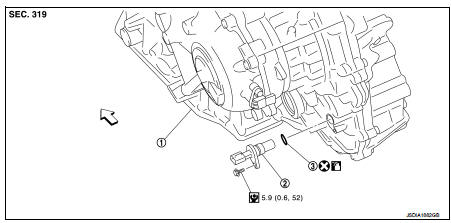
1. Transaxle assembly
2. Output speed sensor
3. O-ring
 : Vehicle front
 : Always replace after every
disassembly.
 : N┬Ěm (kg-m, in-lb)
 : Genuine NISSAN CVT Fluid NS-2
Removal and Installation
REMOVAL
1. Disconnect battery cable from negative terminal. Refer to PG-124, "Removal and Installation".
2. Disconnect the output speed sensor connector.
NOTE
:
Lift up the vehicle and perform the work from rear of the unit.
3. Remove the output speed sensor.
4. Remove the O-ring from the output speed sensor.
INSTALLATION
Note the following, and install in the reverse order of removal.
CAUTION:
ÔÇó Never reuse O-ring.
ÔÇó Apply Genuine NISSAN CVT Fluid NS-2 to the O-ring.
Inspection and Adjustment
INSPECTION AFTER INSTALLATION
Check for CVT fluid leakage. Refer to TM-480, "Inspection".
ADJUSTMENT AFTER INSTALLATION
Check the CVT fluid level. Refer to TM-379, "Adjustment".
 Secondary speed sensor
Exploded View
1. Transaxle assembly
2. O-ring
3. Secondary speed sensor
: Vehicle front
: Always replace after every
disassembly.
: N┬Ěm (kg-m, in-lb)
: Genuine NISSAN CVT Fluid NS-2
Rem ...
 Differential side oil seal
Exploded View
1. Transaxle assembly
2. Differential side oil seal (left side)
3. Differential side oil seal (right side)
: Vehicle front
: Always replace after every
disassembly.
: Genuine N ...
Other materials:
System
WITH AUTO A/C
WITH AUTO A/C : System Diagram
WITH AUTO A/C : System Description
OPERATION DESCRIPTION
ÔÇó BCM detects that the rear window defogger switch turns ON when the ignition
switch is ON, and then transmits
the rear window defogger switch signal to IPDM E/R via CAN communication for ...
ESP off indicator lamp
Component Function Check
1.CHECK ESP OFF INDICATOR LAMP FUNCTION (1)
Check that ESP OFF indicator lamp in combination meter turns ON for approx. 1
second after ignition switch is
turned ON.
CAUTION:
Never start engine.
Is the inspection result normal?
YES >> GO TO 2.
NO >> ...
Diagnosis and repair work flow
Work Flow
OVERALL SEQUENCE
DETAILED FLOW
1.GET INFORMATION ABOUT SYMPTOM
Get detailed information from the customer about the symptom (the condition
and the environment when the
incident/malfunction occurs).
>> GO TO 2.
2.CHECK DTC
1. Check DTC of ÔÇťENGINEÔÇŁ, ÔÇťBCMÔÇŁ and ÔÇ ...
