Nissan Juke Service and Repair Manual : Secondary speed sensor
Exploded View
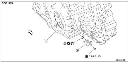
1. Transaxle assembly
2. O-ring
3. Secondary speed sensor
 : Vehicle front
 : Always replace after every
disassembly.
 : N·m (kg-m, in-lb)
 : Genuine NISSAN CVT Fluid NS-2
Removal and Installation
REMOVAL
1. Disconnect battery cable from negative terminal. Refer to PG-124, "Removal and Installation".
2. Remove the air cleaner case. Refer to EM-161, "Removal and Installation".
3. Disconnect the secondary speed sensor connector.
4. Remove the secondary speed sensor.
5. Remove the O-ring from the secondary speed sensor.
INSTALLATION
Note the following, and install in the reverse order of removal.
CAUTION:
• Never reuse O-ring.
• Apply Genuine NISSAN CVT Fluid NS-2 to the O-ring.
Inspection and Adjustment
INSPECTION AFTER INSTALLATION
Check for CVT fluid leakage. Refer to TM-480, "Inspection".
ADJUSTMENT AFTER INSTALLATION
Adjust the CVT fluid level. Refer to TM-379, "Adjustment".
 Primary speed sensor
Exploded View
1. Transaxle assembly
2. O-ring
3. Primary speed sensor
: Always replace after every
disassembly.
: N m (kg-m, in-lb)
: Genuine NISSAN CVT Fluid NS-2
Removal and Installatio ...
 Output speed sensor
Exploded View
1. Transaxle assembly
2. Output speed sensor
3. O-ring
: Vehicle front
: Always replace after every
disassembly.
: N·m (kg-m, in-lb)
: Genuine NISSAN CVT Fluid NS-2
Remova ...
Other materials:
B210B starter control relay
DTC Logic
DTC DETECTION LOGIC
NOTE:
If DTC B210B is displayed with DTC U1000, first perform the trouble diagnosis
for DTC U1000. Refer to PCS-
30, "DTC Logic".
DTC CONFIRMATION PROCEDURE
1.PERFORM DTC CONFIRMATION PROCEDURE
1. Press push-button ignition switch under the followin ...
EPS warning lamp
Component Function Check
1.CHECK THE ILLUMINATION OF THE EPS WARNING LAMP
Check that the EPS warning lamp turns ON when ignition switch turns ON. Then,
EPS warning lamp turns
OFF after the engine is started.
Is the inspection result normal?
YES >> INSPECTION END
NO >> Perform t ...
B1132 side air bag module RH
DTC Logic
DTC DETECTION LOGIC
DTC CONFIRMATION PROCEDURE
1.CHECK SELF-DIAG RESULT
With CONSULT-III
1. Turn ignition switch ON.
2. Perform “Self Diagnostic Result” mode of “AIR BAG” using CONSULT-III.
Without CONSULT-III
1. Turn ignition switch ON.
2. Check the air bag warning la ...
