Nissan Juke Service and Repair Manual : Primary speed sensor
Exploded View
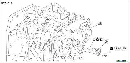
1. Transaxle assembly
2. O-ring
3. Primary speed sensor
 : Always replace after every
disassembly.
 : N m (kg-m, in-lb)
 : Genuine NISSAN CVT Fluid NS-2
Removal and Installation
REMOVAL
1. Remove the battery. Refer to PG-124, "Removal and Installation".
2. Remove the air cleaner case. Refer to EM-161, "Removal and Installation".
3. Remove the ECM and bracket as a set.
4. Disconnect the primary speed sensor connector.
5. Remove the primary speed sensor.
6. Remove the O-ring from the primary speed sensor.
INSTALLATION
Note the following, and install in the reverse order of removal.
CAUTION:
• Never reuse O-ring.
• Apply Genuine NISSAN CVT Fluid NS-2 to the O-ring.
Inspection and Adjustment
INSPECTION AFTER INSTALLATION Check for CVT fluid leakage. Refer to TM-480, "Inspection".
ADJUSTMENT AFTER INSTALLATION Adjust the CVT fluid level. Refer to TM-379, "Adjustment".
 Oil pan
Exploded View
1. Transaxle assembly
2. Oil pan gasket
3. Magnet
4. Oil pan
5. Overflow tube
6. Drain plug gasket
7. Drain plug
8. Oil pan fitting bolt
: Always replace after every
di ...
 Secondary speed sensor
Exploded View
1. Transaxle assembly
2. O-ring
3. Secondary speed sensor
: Vehicle front
: Always replace after every
disassembly.
: N·m (kg-m, in-lb)
: Genuine NISSAN CVT Fluid NS-2
Rem ...
Other materials:
Back door opener system
System Diagram
System Description
BACK DOOR OPENER OPERATION
When back door opener switch is pressed, BCM operates back door opener
actuator.
NOTE:
Back door opener actuator is not for locking the back door. The function is only
to open the back door.
OPERATION CONDITION
If the foll ...
How to Follow Test Groups in Trouble Diagnosis
1. Test group number and test group title
• Test group number and test group title are shown in the upper portion of each
test group.
2. Work and diagnosis procedure
• Start to diagnose a problem using procedures indicated in enclosed test
groups.
3. Questions and results
• Ques ...
Front seat belt
Exploded View
1. Adjuster cover
2. Anchor bolt
3. Shoulder anchor
4. Spacer
5. Retaining washer
6. Seat belt adjuster
7. Seat belt pre-tensioner retractor
(Passenger side)
8. Outer anchor
9. Seat belt pre-tensioner retractor
(Driver side)
10. Seat belt buckle
11. Wave washer
&n ...
