Nissan Juke Service and Repair Manual : LAN System can system (type 7)
DTC/CIRCUIT DIAGNOSIS
Main line between IPDM-E and DLC circuit
Diagnosis Procedure
1.CHECK CONNECTOR
1. Turn the ignition switch OFF.
2. Disconnect the battery cable from the negative terminal.
3. Check the following terminals and connectors for damage, bend and loose connection (connector side and harness side).
- Harness connector E105 - Harness connector M77
Is the inspection result normal? YES >> GO TO 2.
NO >> Repair the terminal and connector.
2.CHECK HARNESS CONTINUITY (OPEN CIRCUIT)
1. Disconnect the following harness connectors.
- IPDM E/R
- Harness connectors E105 and M77
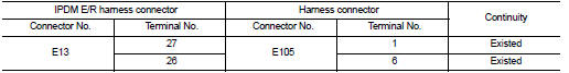
2. Check the continuity between the IPDM E/R harness connector and the harness
connector.
Is the inspection result normal? YES >> GO TO 3.
NO >> Repair the main line between the IPDM E/R and the harness connector E105.
3.CHECK HARNESS CONTINUITY (OPEN CIRCUIT)
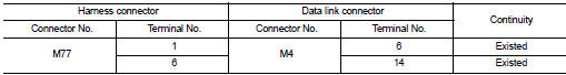
Check the continuity between the harness connector and the data link connector.
Is the inspection result normal? YES (Present error)>>Check CAN system type decision again.
YES (Past error)>>Error was detected in the main line between the IPDM E/R and the data link connector.
NO >> Repair the main line between the harness connector M77 and the data link connector.
Main line between DLC and MDU circuit
Diagnosis Procedure
1.CHECK HARNESS CONTINUITY (OPEN CIRCUIT)
1. Turn the ignition switch OFF.
2. Disconnect the battery cable from the negative terminal.
3. Disconnect the following harness connectors.
- ECM
- Multi display unit
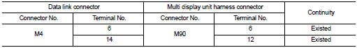
4. Check the continuity between the data link connector and the multi display
unit harness connector.
Is the inspection result normal? YES (Present error)>>Check CAN system type decision again.
YES (Past error)>>Error was detected in the main line between the the data link connector and the multi display unit.
NO >> Repair the main line between the data link connector and the multi display unit.
 LAN System can system (type 6)
DTC/CIRCUIT DIAGNOSIS
Main line between IPDM-E and DLC circuit
Diagnosis Procedure
1.CHECK CONNECTOR
1. Turn the ignition switch OFF.
2. Disconnect the battery cable from the negative terminal.
...
 ECM branch line circuit
Diagnosis Procedure
1.CHECK CONNECTOR
1. Turn the ignition switch OFF.
2. Disconnect the battery cable from the negative terminal.
3. Check the terminals and connectors of the ECM for damage, bend ...
Other materials:
System
ENGINE CONTROL SYSTEM : System Diagram
1. Priming pump
2. Fuel filter
3. High pressure supply pump
4. High pressure supply pump (internal
transfer pump)
5. High pressure supply pump (volumetric
control valve)
6. High pressure supply pump (high
pressure pump)
7. High pressure supply pum ...
Insufficient cooling
Description
Symptom
• Insufficient cooling
• No cool air comes out. (Air flow volume is normal.)
Diagnosis Procedure
NOTE:
Perform self-diagnoses with CONSULT-III before performing symptom diagnosis. If
any DTC is detected, perform
the corresponding diagnosis.
1.CHECK MAGNET CLUTCH O ...
B2623 inside antenna
DTC Logic
DTC DETECTION LOGIC
DTC CONFIRMATION PROCEDURE
1.PERFORM DTC CONFIRMATION PROCEDURE
1. Select “INTELLIGENT KEY” of “BCM” using CONSULT-III.
2. Select “INSIDE ANT DIAGNOSIS” in “WORK SUPPORT” mode.
3. Perform inside key antenna (“INSIDE ANT DIAGNOSIS”) on “WORK ...
