Nissan Juke Service and Repair Manual : ECM branch line circuit
Diagnosis Procedure
1.CHECK CONNECTOR
1. Turn the ignition switch OFF.
2. Disconnect the battery cable from the negative terminal.
3. Check the terminals and connectors of the ECM for damage, bend and loose connection (unit side and connector side).
Is the inspection result normal? YES >> GO TO 2.
NO >> Repair the terminal and connector.
2.CHECK HARNESS FOR OPEN CIRCUIT
1. Disconnect the connector of ECM.
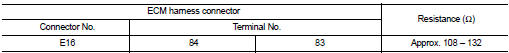
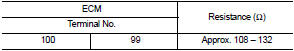
2. Check the resistance between the ECM harness connector terminals.
- HR16DE models
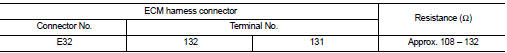
- MR16DDT models

- K9K models
Is the measurement value within the specification? YES >> GO TO 3.
NO >> Repair the ECM branch line.
3.CHECK POWER SUPPLY AND GROUND CIRCUIT
Check the power supply and the ground circuit of the ECM. Refer to the following.
• HR16DE: EC-566, "Diagnosis Procedure" • MR16DDT: EC-155, "Diagnosis Procedure" • K9K: EC-885, "Diagnosis Procedure"
Is the inspection result normal? YES (Present error)>>Replace the ECM. Refer to the following.
• HR16DE: EC-805, "Removal and Installation" • MR16DDT: EC-447, "Removal and Installation" • K9K: EC-879, "Work Procedure"
YES (Past error)>>Error was detected in the ECM branch line.
NO >> Repair the power supply and the ground circuit.
ABS branch line circuit
Diagnosis Procedure
1.CHECK CONNECTOR
1. Turn the ignition switch OFF.
2. Disconnect the battery cable from the negative terminal.
3. Check the terminals and connectors of the ABS actuator and electric unit (control unit) for damage, bend and loose connection (unit side and connector side).
Is the inspection result normal? YES >> GO TO 2.
NO >> Repair the terminal and connector.
2.CHECK HARNESS FOR OPEN CIRCUIT
1. Disconnect the connector of ABS actuator and electric unit (control unit).
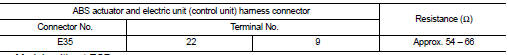
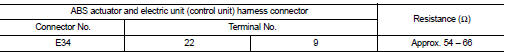
2. Check the resistance between the ABS actuator and electric unit (control unit) harness connector terminals.
- Models with ESP
- Models without ESP
Is the measurement value within the specification? YES >> GO TO 3.
NO >> Repair the ABS actuator and electric unit (control unit) branch line.
3.CHECK POWER SUPPLY AND GROUND CIRCUIT
Check the power supply and the ground circuit of the ABS actuator and electric unit (control unit). Refer to the following.
• Models without ESP: BRC-64, "Diagnosis Procedure" • Models with ESP: BRC-205, "Diagnosis Procedure"
Is the inspection result normal? YES (Present error)>>Replace the ABS actuator and electric unit (control unit). Refer to the following.
• Models without ESP: BRC-90, "Removal and Installation".
• Models with ESP: BRC-233, "Removal and Installation".
YES (Past error)>>Error was detected in the ABS actuator and electric unit (control unit) branch line.
NO >> Repair the power supply and the ground circuit.
IPDM-E branch line circuit
Diagnosis Procedure
1.CHECK CONNECTOR
1. Turn the ignition switch OFF.
2. Disconnect the battery cable from the negative terminal.
3. Check the terminals and connectors of the IPDM E/R for damage, bend and loose connection (unit side and connector side).
Is the inspection result normal? YES >> GO TO 2.
NO >> Repair the terminal and connector.
2.CHECK HARNESS FOR OPEN CIRCUIT
1. Disconnect the connector of IPDM E/R.
2. Check the resistance between the IPDM E/R harness connector terminals.
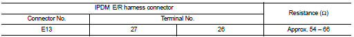
Is the measurement value within the specification? YES >> GO TO 3.
NO >> Repair the IPDM E/R branch line.
3.CHECK POWER SUPPLY AND GROUND CIRCUIT
Check the power supply and the ground circuit of the IPDM E/R. Refer to the following.
• Models with Intelligent Key system: PCS-33, "Diagnosis Procedure" • Models without Intelligent Key system: PCS-62, "Diagnosis Procedure"
Is the inspection result normal? YES (Present error)>>Replace the IPDM E/R. Refer to the following.
• Models with Intelligent Key system: PCS-34, "Removal and Installation" • Models without Intelligent Key system: PCS-63, "Removal and Installation"
YES (Past error)>>Error was detected in the IPDM E/R branch line.
NO >> Repair the power supply and the ground circuit.
TCM branch line circuit
Diagnosis Procedure
1.CHECK CONNECTOR
1. Turn the ignition switch OFF.
2. Disconnect the battery cable from the negative terminal.
3. Check the following terminals and connectors for damage, bend and loose connection (unit side and connector side).
- TCM
- Harness connecotor F1
- Harness connecotor E8
Is the inspection result normal? YES >> GO TO 2.
NO >> Repair the terminal and connector.
2.CHECK HARNESS FOR OPEN CIRCUIT
1. Disconnect the connector of TCM.
2. Check the resistance between the TCM harness connector terminals.
- HR16DE models
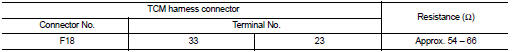
- MR16DDT models
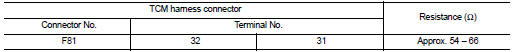
Is the measurement value within the specification? YES >> GO TO 3.
NO >> Repair the TCM branch line. 3.CHECK POWER SUPPLY AND GROUND CIRCUIT
Check the power supply and the ground circuit of the TCM. Refer to the following.
• HR16DE: TM-464, "Diagnosis Procedure" • MR16DDT: TM-239, "Diagnosis Procedure"
Is the inspection result normal? YES (Present error)>>Replace the TCM. Refer to the following.
• HR16DE: TM-490, "Removal and Installation" • MR16DDT: TM-280, "Removal and Installation"
YES (Past error)>>Error was detected in the TCM branch line.
NO >> Repair the power supply and the ground circuit.
DLC branch line circuit
Diagnosis Procedure
1.CHECK CONNECTOR
1. Turn the ignition switch OFF.
2. Disconnect the battery cable from the negative terminal.
3. Check the terminals and connectors of the data link connector for damage, bend and loose connection (connector side and harness side).
Is the inspection result normal? YES >> GO TO 2.
NO >> Repair the terminal and connector.
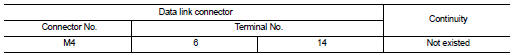
2.CHECK HARNESS FOR OPEN CIRCUIT
Check the resistance between the data link connector terminals.
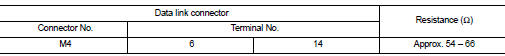
Is the measurement value within the specification? YES (Present error)>>Check CAN system type decision again.
YES (Past error)>>Error was detected in the data link connector branch line circuit.
NO >> Repair the data link connector branch line.
EPS branch line circuit
Diagnosis Procedure
1.CHECK CONNECTOR
1. Turn the ignition switch OFF.
2. Disconnect the battery cable from the negative terminal.
3. Check the terminals and connectors of the EPS control unit for damage, bend and loose connection (unit side and connector side).
Is the inspection result normal? YES >> GO TO 2.
NO >> Repair the terminal and connector.
2.CHECK HARNESS FOR OPEN CIRCUIT
1. Disconnect the connector of EPS control unit.
2. Check the resistance between the EPS control unit harness connector terminals.
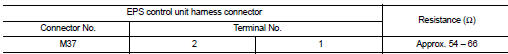
Is the measurement value within the specification? YES >> GO TO 3.
NO >> Repair the EPS control unit branch line.
3.CHECK POWER SUPPLY AND GROUND CIRCUIT
Check the power supply and the ground circuit of the EPS control unit. Refer to STC-19, "Diagnosis Procedure".
Is the inspection result normal? YES (Present error)>>Replace the EPS control unit. Refer to STC-32, "Removal and Installation".
YES (Past error)>>Error was detected in the EPS control unit branch line.
NO >> Repair the power supply and the ground circuit.
M&A branch line circuit
Diagnosis Procedure
1.CHECK CONNECTOR
1. Turn the ignition switch OFF.
2. Disconnect the battery cable from the negative terminal.
3. Check the terminals and connectors of the combination meter for damage, bend and loose connection (unit side and connector side).
Is the inspection result normal? YES >> GO TO 2.
NO >> Repair the terminal and connector.
2.CHECK HARNESS FOR OPEN CIRCUIT
1. Disconnect the connector of combination meter.
2. Check the resistance between the combination meter harness connector terminals.
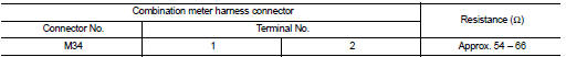
Is the measurement value within the specification? YES >> GO TO 3.
NO >> Repair the combination meter branch line.
3.CHECK POWER SUPPLY AND GROUND CIRCUIT
Check the power supply and the ground circuit of the combination meter. Refer to MWI-51, "COMBINATION METER : Diagnosis Procedure".
Is the inspection result normal? YES (Present error)>>Replace the combination meter. Refer to MWI-69, "Removal and Installation".
YES (Past error)>>Error was detected in the combination meter branch line.
NO >> Repair the power supply and the ground circuit.
STRG branch line circuit
Diagnosis Procedure
1.CHECK CONNECTOR
1. Turn the ignition switch OFF.
2. Disconnect the battery cable from the negative terminal.
3. Check the terminals and connectors of the steering angle sensor for damage, bend and loose connection (unit side and connector side).
Is the inspection result normal? YES >> GO TO 2.
NO >> Repair the terminal and connector.
2.CHECK HARNESS FOR OPEN CIRCUIT
1. Disconnect the connector of steering angle sensor.
2. Check the resistance between the steering angle sensor harness connector terminals.
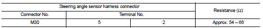
Is the measurement value within the specification? YES >> GO TO 3.
NO >> Repair the steering angle sensor branch line.
3.CHECK POWER SUPPLY AND GROUND CIRCUIT
Check the power supply and the ground circuit of the steering angle sensor. Refer to BRC-144, "Wiring Diagram".
Is the inspection result normal? YES (Present error)>>Replace the steering angle sensor. Refer to BRC-236, "Removal and Installation".
YES (Past error)>>Error was detected in the steering angle sensor branch line.
NO >> Repair the power supply and the ground circuit.
A-BAG branch line circuit
Diagnosis Procedure
WARNING:
• Before servicing, turn ignition switch OFF, disconnect battery negative
terminal, and wait 3 minutes
or more. (To discharge backup capacitor.)
• Never use unspecified tester or other measuring device.
1.CHECK CONNECTOR
1. Turn the ignition switch OFF.
2. Disconnect the battery cable from the negative terminal.
3. Check the terminals and connectors of the air bag diagnosis sensor unit for damage, bend and loose connection (unit side and connector side).
Is the inspection result normal? YES >> GO TO 2.
NO >> Replace the main harness.
2.CHECK AIR BAG DIAGNOSIS SENSOR UNIT
Check the air bag diagnosis sensor unit. Refer to SRC-24, "Work Flow".
Is the inspection result normal? YES >> Replace the main harness.
NO >> Replace parts whose air bag system has a malfunction
MDU branch line circuit
Diagnosis Procedure
1.CHECK CONNECTOR
1. Turn the ignition switch OFF.
2. Disconnect the battery cable from the negative terminal.
3. Check the terminals and connectors of the multi display unit for damage, bend and loose connection (unit side and connector side).
Is the inspection result normal? YES >> GO TO 2.
NO >> Repair the terminal and connector.
2.CHECK HARNESS FOR OPEN CIRCUIT
1. Disconnect the connector of multi display unit.
2. Check the resistance between the multi display unit harness connector terminals
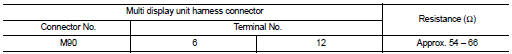
Is the measurement value within the specification? YES >> GO TO 3.
NO >> Repair the multi display unit branch line.
3.CHECK POWER SUPPLY AND GROUND CIRCUIT
Check the power supply and the ground circuit of the multi display unit. Refer to AV-123, "MULTI DISPLAY UNIT : Diagnosis Procedure".
Is the inspection result normal? YES (Present error)>>Replace the multi display unit. Refer to DMS-13, "Removal and Installation".
YES (Past error)>>Error was detected in the multi display unit branch line.
NO >> Repair the power supply and the ground circuit.
BCM branch line circuit
Diagnosis Procedure
1.CHECK CONNECTOR
1. Turn the ignition switch OFF.
2. Disconnect the battery cable from the negative terminal.
3. Check the terminals and connectors of the BCM for damage, bend and loose connection (unit side and connector side).
Is the inspection result normal? YES >> GO TO 2.
NO >> Repair the terminal and connector.
2.CHECK HARNESS FOR OPEN CIRCUIT
1. Disconnect the connector of BCM.
2. Check the resistance between the BCM harness connector terminals.
- Models with Intelligent Key system

- Models without Intelligent Key system
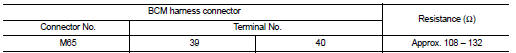
Is the measurement value within the specification? YES >> GO TO 3.
NO >> Repair the BCM branch line.
3.CHECK POWER SUPPLY AND GROUND CIRCUIT
Check the power supply and the ground circuit of the BCM. Refer to the following.
• Models with Intelligent Key system: BCS-87, "Diagnosis Procedure" • Models without Intelligent Key system: BCS-155, "Diagnosis Procedure"
Is the inspection result normal? YES (Present error)>>Replace the BCM. Refer to the following.
• Models with Intelligent Key system: BCS-93, "Removal and Installation" • Models without Intelligent Key system: BCS-161, "Removal and Installation"
YES (Past error)>>Error was detected in the BCM branch line.
NO >> Repair the power supply and the ground circuit
Can communication circuit
Diagnosis Procedure
1.CONNECTOR INSPECTION
1. Turn the ignition switch OFF.
2. Disconnect the battery cable from the negative terminal.
3. Disconnect all the unit connectors on CAN communication system.
4. Check terminals and connectors for damage, bend and loose connection.
Is the inspection result normal? YES >> GO TO 2.
NO >> Repair the terminal and connector.
2.CHECK HARNESS CONTINUITY (SHORT CIRCUIT)
Check the continuity between the data link connector terminals.
Is the inspection result normal? YES >> GO TO 3.
NO >> Check the harness and repair the root cause.
3.CHECK HARNESS CONTINUITY (SHORT CIRCUIT)
Check the continuity between the data link connector and the ground.
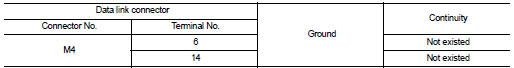
Is the inspection result normal? YES >> GO TO 4.
NO >> Check the harness and repair the root cause.
4.CHECK ECM AND BCM TERMINATION CIRCUIT
1. Remove the ECM and the BCM.
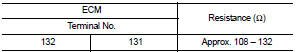
2. Check the resistance between the ECM terminals.
- HR16DE models
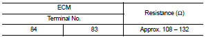
- MR16DDT models
- K9K models
3. Check the resistance between the BCM terminals.
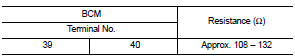
Is the measurement value within the specification? YES >> GO TO 5.
NO >> Replace the ECM and/or the BCM.
5.CHECK SYMPTOM
Connect all the connectors. Check if the symptoms described in the “Symptom (Results from interview with customer)” are reproduced.
Inspection result Reproduced>>GO TO 6.
Non-reproduced>>Start the diagnosis again. Follow the trouble diagnosis procedure when past error is detected.
6.CHECK UNIT REPRODUCTION
Perform the reproduction test as per the following procedure for each unit.
1. Turn the ignition switch OFF.
2. Disconnect the battery cable from the negative terminal.
3. Disconnect one of the unit connectors of CAN communication system.
NOTE
:
ECM and BCM have a termination circuit. Check other units first.
4. Connect the battery cable to the negative terminal. Check if the symptoms described in the “Symptom (Results from interview with customer)” are reproduced.
NOTE
:
Although unit-related error symptoms occur, do not confuse them with other
symptoms.
Inspection result Reproduced>>Connect the connector. Check other units as per the above procedure.
Non-reproduced>>Replace the unit whose connector was disconnected.
 LAN System can system (type 7)
DTC/CIRCUIT DIAGNOSIS
Main line between IPDM-E and DLC circuit
Diagnosis Procedure
1.CHECK CONNECTOR
1. Turn the ignition switch OFF.
2. Disconnect the battery cable from the negative terminal.
...
 LAN System can system (type 8)
DTC/CIRCUIT DIAGNOSIS
Main line between IPDM-E and DLC circuit
Diagnosis Procedure
1.CHECK CONNECTOR
1. Turn the ignition switch OFF.
2. Disconnect the battery cable from the negative terminal.
...
Other materials:
Exterior front
1. Hood
2. Windshield wiper and washer
— Switch operation
— Blade replacement
— Window washer fluid
3. Parking lights, turn signal lights and front side marker lights
— Switch operation
— Bulb replacement
4. Moonroof
5. Side turn signal lights
— Switch operation
— ...
P0713 transmission fluid temperature sensor A
DTC Logic
DTC CONFIRMATION PROCEDURE
1.PREPARATION BEFORE WORK
If another "DTC CONFIRMATION PROCEDURE" occurs just before, turn ignition
switch OFF and wait for at
least 10 seconds, then perform the next test.
>> GO TO 2.
2.PERFORM DTC CONFIRMATION PROCEDURE
1. Start the ...
Unexpected brake pedal reaction
Description
A malfunction of brake pedal feel (height or others) is detected when brake
pedal is depressed.
Diagnosis Procedure
1.CHECK FRONT AND REAR AXLE
Check that there is no excessive looseness in front and rear axle.
• Front axle: Refer to FAX-41, "Inspection".
• Rear a ...
