Nissan Juke Service and Repair Manual : Door request switch
Component Function Check
1.CHECK FUNCTION
1. Select ÔÇťINTELLIGENT KEYÔÇŁ of ÔÇťBCMÔÇŁ using CONSULT-III.
2. Select ÔÇťREQ SW-DRÔÇŁ, ÔÇťREQ SW-ASÔÇŁ in ÔÇťDATA MONITORÔÇŁ mode.
3. Check that the function operates normally according to the following conditions.
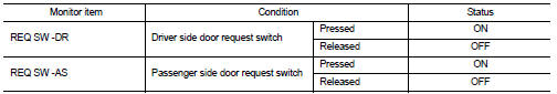
Is the inspection result normal? YES >> Front door request switch is OK.
NO >> Refer to DLK-85, "Diagnosis Procedure".
Diagnosis Procedure
1.CHECK DOOR REQUEST SWITCH INPUT SIGNAL
1. Turn ignition switch OFF.
2. Disconnect malfunctioning front door request switch connector.
3. Check voltage between malfunctioning front door request switch harness connector and ground.
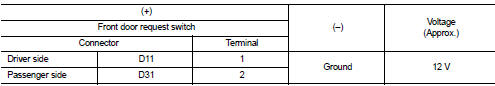
Is the inspection result normal? YES >> GO TO 3.
NO >> GO TO 2.
2.CHECK DOOR REQUEST SWITCH CIRCUIT
1. Disconnect BCM connector.
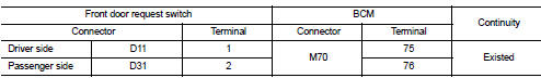
2. Check continuity between malfunctioning front door request switch harness connector and BCM harness connector.
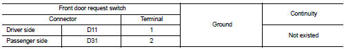
3. Check continuity between malfunctioning front door request switch harness connector and ground.
Is the inspection result normal? YES >> Replace BCM. Refer to BCS-93, "Removal and Installation".
NO >> Repair or replace harness.
3.CHECK DOOR REQUEST SWITCH GROUND CIRCUIT
Check continuity between malfunctioning front door request switch harness connector and ground.
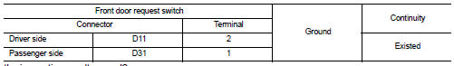
Is the inspection result normal? YES >> GO TO 4.
NO >> Repair or replace harness.
4.CHECK DOOR REQUEST SWITCH
Refer to DLK-86, "Component Inspection".
Is the inspection result normal? YES >> GO TO 5.
NO >> Replace malfunctioning front door request switch.
5.CHECK INTERMITTENT INCIDENT
Refer to GI-42, "Intermittent Incident".
>> INSPECTION END
Component Inspection
1.CHECK DOOR REQUEST SWITCH 1. Turn ignition switch OFF.
2. Disconnect malfunctioning front door request switch connector.
3. Check continuity between malfunctioning front door request switch terminals.
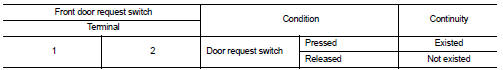
Is the inspection result normal? YES >> INSPECTION END
NO >> Replace malfunctioning front door request switch
 Door lock status indicator
Component Function Check
1.CHECK FUNCTION
1. Select ÔÇťDOOR LOCKÔÇŁ of ÔÇťBCMÔÇŁ using CONSULT-III.
2. Select ÔÇťDOOR LOCK INDÔÇŁ in ÔÇťACTIVE TESTÔÇŁ mode.
3. Check that the function operates nor ...
 Door switch
Component Function Check
1.CHECK FUNCTION
1. Select ÔÇťDOOR LOCKÔÇŁ of ÔÇťBCMÔÇŁ using CONSULT-III.
2. Select ÔÇťDOOR SW-DRÔÇŁ, ÔÇťDOOR SW-ASÔÇŁ, ÔÇťDOOR SW-RLÔÇŁ, ÔÇťDOOR SW-RRÔÇŁ, ÔÇťDOOR SW-BKÔÇ ...
Other materials:
Engine block heater (if so equipped)
Engine block heaters are used to assist in cold temperature starting.
The engine block heater should be used when the outside temperature is 208F (−78C)
or lower.
To use the engine block heater
1. Turn the engine off.
2. Open the hood and unwrap the engine block heater cord.
3. Plug the ...
P2122, P2123 APP sensor
DTC Logic
DTC DETECTION LOGIC
NOTE:
If DTC P2122 or P2123 is displayed with DTC P0643, first perform the trouble
diagnosis for DTC P0643.
Refer to EC-307, "DTC Logic".
DTC CONFIRMATION PROCEDURE
1.PRECONDITIONING
If DTC Confirmation Procedure has been previously conducted, alw ...
B2603 shift position
DTC Logic
DTC DETECTION LOGIC
NOTE:
ÔÇó If DTC B2603 is displayed with DTC B2601, first perform the trouble diagnosis
for DTC B2601. Refer to
SEC-79, "DTC Logic".
DTC CONFIRMATION PROCEDURE
1.PERFORM DTC CONFIRMATION PROCEDURE 1
1. Shift the selector lever to the P position.
2. ...
