Nissan Juke Service and Repair Manual : Door lock status indicator
Component Function Check
1.CHECK FUNCTION
1. Select “DOOR LOCK” of “BCM” using CONSULT-III.
2. Select “DOOR LOCK IND” in “ACTIVE TEST” mode.
3. Check that the function operates normally according to the following conditions.
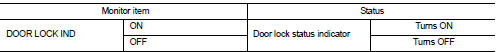
Is the inspection result normal? YES >> Door lock status indicator is OK.
NO >> Refer to DLK-83, "Diagnosis Procedure".
Diagnosis Procedure
1.CHECK DOOR LOCK STATUS INDICATOR INPUT SIGNAL
1. Turn ignition switch OFF.
2. Disconnect door lock status indicator connector.
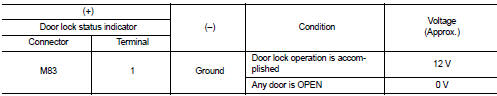
3. Check voltage between door lock status indicator harness connector and ground.
Is the inspection result normal? YES >> GO TO 3.
NO >> GO TO 2.
2.CHECK DOOR LOCK STATUS INDICATOR CIRCUIT
1. Disconnect BCM connector.
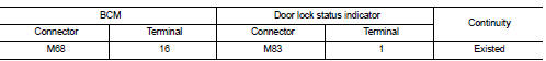
2. Check continuity between BCM harness connector and door lock status indicator harness connector.
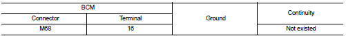
3. Check continuity between BCM harness connector and ground.
Is the inspection result normal? YES >> Replace BCM. Refer to BCS-93, "Removal and Installation".
NO >> Repair or replace harness.
3.CHECK DOOR LOCK STATUS INDICATOR GROUND
Check continuity between door lock status indicator harness connector and ground.
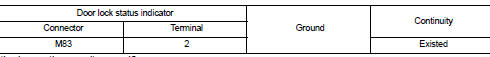
Is the inspection result normal? YES >> Replace door lock status indicator.
NO >> Repair or replace harness.
 Door lock and unlock switch
Driver side : Component Function Check
1.CHECK FUNCTION
1. Select “DOOR LOCK” of “BCM” using CONSULT-III.
2. Select “CDL LOCK SW”, “CDL UNLOCK SW” in “DATA MONITOR” mode.
3. Ch ...
 Door request switch
Component Function Check
1.CHECK FUNCTION
1. Select “INTELLIGENT KEY” of “BCM” using CONSULT-III.
2. Select “REQ SW-DR”, “REQ SW-AS” in “DATA MONITOR” mode.
3. Check that the f ...
Other materials:
Wheels
Wash the wheels when washing the vehicle to maintain their appearance.
• Clean the inner side of the wheels when the wheel is changed or the underside
of the vehicle is washed.
• Inspect wheel rims regularly for dents or corrosion. Such damage may cause loss
of pressure or poor seal at the ...
Automatic climate control
(models without Navigation System)
fan speed control dial
intake air control
button
front defroster button
Climate Ctrl. display (dedicated monochromatic status screen for reading target t ...
NISSAN Advanced Air Bag System (front seats)
Crash zone sensor
Supplemental front-impact air bag modules
Front seat-mounted side-impact supplemental air bag modules
Occupant classification sensor (weight sensor)
Occupant classification system control unit
Roof-mounted ...
