Nissan Juke Service and Repair Manual : Door lock and unlock switch
Driver side : Component Function Check
1.CHECK FUNCTION
1. Select ÔÇťDOOR LOCKÔÇŁ of ÔÇťBCMÔÇŁ using CONSULT-III.
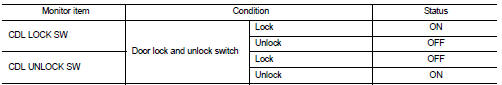
2. Select ÔÇťCDL LOCK SWÔÇŁ, ÔÇťCDL UNLOCK SWÔÇŁ in ÔÇťDATA MONITORÔÇŁ mode.
3. Check that the function operates normally according to the following conditions.
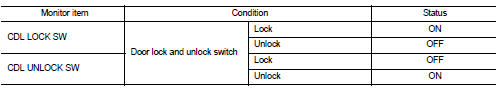
Is the inspection result normal? YES >> Door lock and unlock switch is OK.
NO >> Refer to DLK-79, "DRIVER SIDE : Diagnosis Procedure".
Driver side : Diagnosis Procedure
1.CHECK DOOR LOCK AND UNLOCK SWITCH INPUT SIGNAL
1. Turn ignition switch OFF.
2. Disconnect power window main switch connector.
3. Check signal between power window main switch harness connector and ground using oscilloscope.
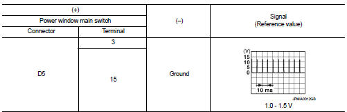
Is the inspection result normal? YES >> GO TO 3.
NO >> GO TO 2.
2.CHECK DOOR LOCK AND UNLOCK SWITCH CIRCUIT
1. Disconnect BCM connector and front power window switch (passenger side) connector.
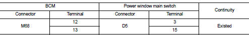
2. Check continuity between BCM harness connector and power window main switch harness connector.
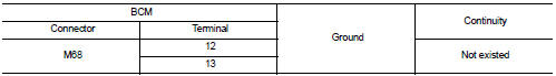
3. Check continuity between BCM harness connector and ground.
Is the inspection result normal? YES >> Replace BCM. Refer to BCS-93, "Removal and Installation".
NO >> Repair or replace harness.
3.CHECK DOOR LOCK AND UNLOCK SWITCH GROUND
Check continuity between power window main switch harness connector and ground.
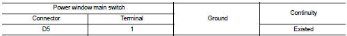
Is the inspection result normal? YES >> GO TO 4.
NO >> Repair or replace harness.
4.CHECK DOOR LOCK AND UNLOCK SWITCH
Refer to DLK-80, "DRIVER SIDE : Component Inspection".
Is the inspection result normal? YES >> GO TO 5.
NO >> Replace power window main switch. Refer to PWC-44, "Removal and Installation".
5.CHECK INTERMITTENT INCIDENT
Refer to GI-42, "Intermittent Incident".
>> INSPECTION END
Driver side : Component Inspection
1.CHECK DOOR LOCK AND UNLOCK SWITCH
1. Turn ignition switch OFF.
2. Disconnect power window main switch connector.
3. Check continuity between power window main switch terminals.
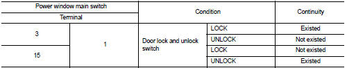
Is the inspection result normal? YES >> INSPECTION END
NO >> Replace power window main switch.
Passenger side : Component Function Check
1.CHECK FUNCTION
1. Select ÔÇťDOOR LOCKÔÇŁ of ÔÇťBCMÔÇŁ using CONSULT-III.
2. Select ÔÇťCDL LOCK SWÔÇŁ, ÔÇťCDL UNLOCK SWÔÇŁ in ÔÇťDATA MONITORÔÇŁ mode.
3. Check that the function operates normally according to the following conditions.
Is the inspection result normal? YES >> Door lock and unlock switch is OK.
NO >> Refer to DLK-81, "PASSENGER SIDE : Diagnosis Procedure".
Passenger side : Diagnosis Procedure
1.CHECK DOOR LOCK AND UNLOCK SWITCH INPUT SIGNAL
1. Turn ignition switch OFF.
2. Disconnect front power window switch (passenger side) connector.
3. Check signal between front power window switch (passenger side) harness connector and ground using oscilloscope.
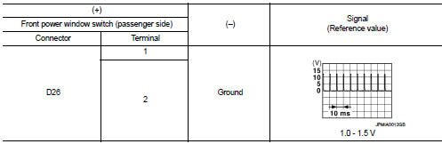
Is the inspection result normal? YES >> GO TO 3.
NO >> GO TO 2.
2.CHECK DOOR LOCK AND UNLOCK SWITCH CIRCUIT
1. Disconnect BCM connector and power window main switch connector.
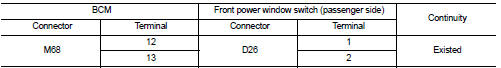
2. Check continuity between BCM harness connector and front power window switch (passenger side) harness connector.
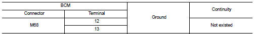
3. Check continuity between BCM harness connector and ground.
Is the inspection result normal? YES >> Replace BCM. Refer to BCS-93, "Removal and Installation".
NO >> Repair or replace harness.
3.CHECK DOOR LOCK AND UNLOCK SWITCH GROUND
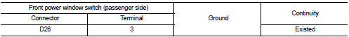
Check continuity between front power window switch (passenger side) harness connector and ground.
Is the inspection result normal? YES >> GO TO 4.
NO >> Repair or replace harness.
4.CHECK DOOR LOCK AND UNLOCK SWITCH
Refer to DLK-82, "PASSENGER SIDE : Component Inspection".
Is the inspection result normal? YES >> GO TO 5.
NO >> Replace front power window switch (passenger side). Refer to PWC-44, "Removal and Installation".
5.CHECK INTERMITTENT INCIDENT
Refer to GI-42, "Intermittent Incident".
>> INSPECTION END
Passenger side : Component Inspection
1.CHECK DOOR LOCK AND UNLOCK SWITCH
1. Turn ignition switch OFF.
2. Disconnect front power window switch (passenger side) connector.
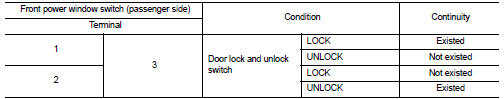
3. Check continuity between front power window switch (passenger side) terminals.
Is the inspection result normal? YES >> INSPECTION END
NO >> Replace front power window switch (passenger side).
 Door lock actuator
Driver side : Component Function Check
1.CHECK FUNCTION
1. Select ÔÇťDOOR LOCKÔÇŁ of ÔÇťBCMÔÇŁ using CONSULT-III.
2. Select ÔÇťDOOR LOCKÔÇŁ in ÔÇťACTIVE TESTÔÇŁ mode.
3. Check that the function op ...
 Door lock status indicator
Component Function Check
1.CHECK FUNCTION
1. Select ÔÇťDOOR LOCKÔÇŁ of ÔÇťBCMÔÇŁ using CONSULT-III.
2. Select ÔÇťDOOR LOCK INDÔÇŁ in ÔÇťACTIVE TESTÔÇŁ mode.
3. Check that the function operates nor ...
Other materials:
P0045 TC boost control solenoid valve
DTC Logic
DTC DETECTION LOGIC
Diagnosis Procedure
1.CHECK TURBOCHARGER BOOST CONTROL SOLENOID VALVE POWER SUPPLY CIRCUIT
1. Turn ignition switch OFF.
2. Disconnect turbocharger boost control solenoid valve harness connector.
3. Turn ignition switch ON.
4. Check the voltage between turbochar ...
Intelligent Blind Spot Intervention (I-BSI)
WARNING
Failure to strictly adhere to these safety warnings and operational instructions for the Intelligent Blind Spot Intervention (I-BSI) system could result in unpredictable vehicle behavior, potentially leading to serious personal injury or fatal accidents.
The I-BSI system ...
Combination switch
Exploded View
1. Combination switch
2. Combination switch connector
Removal and Installation
REMOVAL
1. Remove steering column cover. Refer to IP-13, "Removal and
Installation".
2. Remove screws.
3. Disconnect the connector.
4. Pull up the combination switch to remove it.
I ...
