Nissan Juke Service and Repair Manual : Interior room lamp control system
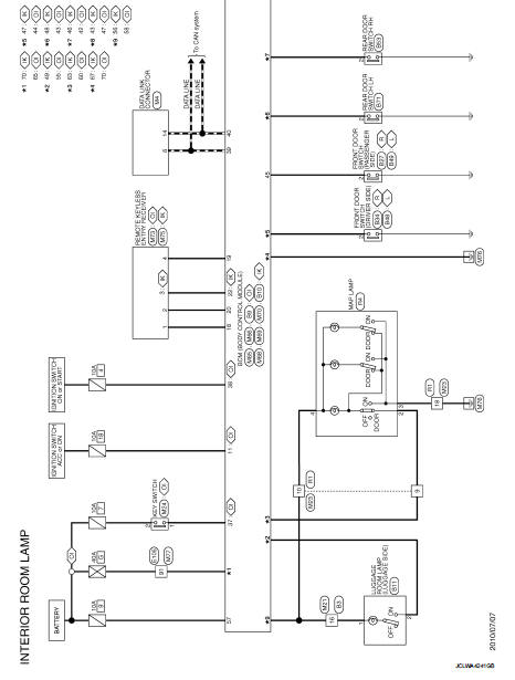
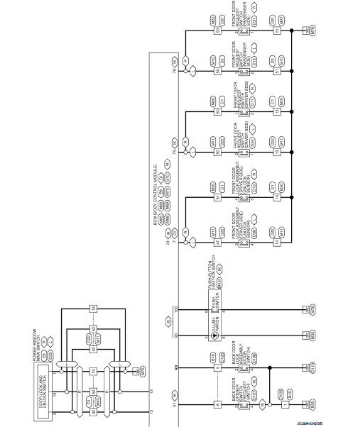
Wiring Diagram
For connector terminal arrangements, harness layouts, and alphabets in a
 (option abbreviation: if not
described in wiring diagram), refer to GI-12, "Connector Information/Explanation
of Option Abbreviation".
 Wiring diagram
...
 Illumination
Wiring Diagram
For connector terminal arrangements, harness layouts, and alphabets in a
(option abbreviation: if not
described in wiring diagram), refer to GI-12, "Connector Information/Explan ...
Other materials:
Additional service when removing battery negative terminal
Description
When the battery negative terminal is disconnected, the initialization is
necessary for normal operation of
power window system.
CAUTION:
The following specified operations can not be performed under the
non-initialized condition.
• Auto-up operation
• Anti-pinch function ...
B2605 shift position
DTC Logic
DTC DETECTION LOGIC
NOTE:
• If DTC B2605 is displayed with DTC U1000, first perform the trouble diagnosis
for DTC U1000. Refer to
BCS-83, "DTC Logic".
• If DTC B2605 is displayed with DTC U1010, first perform the trouble diagnosis
for DTC U1010. Refer to
BCS-84, &qu ...
B2615 blower relay circuit
DTC Logic
DTC DETECTION LOGIC
DTC CONFIRMATION PROCEDURE
1.PERFORM DTC CONFIRMATION PROCEDURE
1. Turn ignition switch ON under the following conditions, and wait for 1
second or more.
CVT models
- Selector lever is in the P or N position
- Do not depress brake pedal
M/T models
- Do no ...
