Nissan Juke Service and Repair Manual : B2615 blower relay circuit
DTC Logic
DTC DETECTION LOGIC
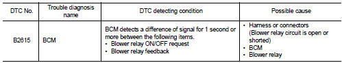
DTC CONFIRMATION PROCEDURE
1.PERFORM DTC CONFIRMATION PROCEDURE
1. Turn ignition switch ON under the following conditions, and wait for 1 second or more.
CVT models
- Selector lever is in the P or N position
- Do not depress brake pedal
M/T models
- Do not depress clutch pedal
2. Check ŌĆ£Self-diagnosis resultŌĆØ of BCM with CONSULT-III.
Is DTC detected? YES >> Go to PCS-94, "Diagnosis Procedure".
NO >> INSPECTION END
Diagnosis Procedure
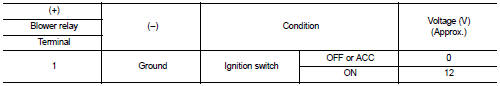
1.CHECK BLOWER RELAY POWER SUPPLY
1. Turn ignition switch OFF.
2. Disconnect blower relay.
3. Check voltage between blower relay harness connector and ground.
Is the inspection result normal? YES >> GO TO 3.
NO >> GO TO 2.
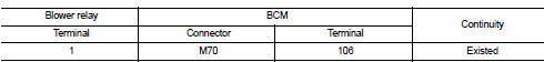
2.CHECK BLOWER RELAY POWER SUPPLY CIRCUIT
1. Turn ignition switch OFF.
2. Disconnect BCM connector.
3. Check continuity between blower relay harness connector and BCM harness connecto
4. Check continuity between blower relay harness connector and ground.

Is the inspection result normal? YES >> GO TO 6.
NO >> Repair or replace harness.
3.CHECK BLOWER RELAY GROUND CIRCUIT
1. Turn ignition switch OFF.
2. Check continuity between blower relay harness connector and ground.

Is the inspection result normal? YES >> GO TO 4.
NO >> Repair blower relay ground circuit.
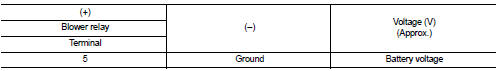
4.CHECK BLOWER RELAY POWER SUPPLY CIRCUIT-2
1. Turn ignition switch ON.
2. Check voltage between blower relay harness connector and ground.
Is the inspection result normal? YES >> GO TO 5.
NO >> Check continuity open or short between blower relay and battery.
5.CHECK BLOWER RELAY
Refer to PCS-95, "Component Inspection".
Is the inspection result normal? YES >> GO TO 6.
NO >> Replace blower relay.
6.CHECK INTERMITTENT INCIDENT
Refer to GI-42, "Intermittent Incident".
>> INSPECTION END
Component Inspection
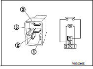
1.CHECK BLOWER RELAY
1. Turn ignition switch OFF.
2. Remove ignition relay.
3. Check the continuity between ignition relay terminals.
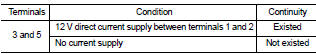
Is the inspection result normal? YES >> INSPECTION END
NO >> Replace Ignition relay
 B2614 ACC relay circuit
DTC Logic
DTC DETECTION LOGIC
DTC CONFIRMATION PROCEDURE
1.PERFORM DTC CONFIRMATION PROCEDURE
1. Turn the power supply position to ACC under the following conditions, and
wait for 2 second or ...
 B2618 BCM
DTC Logic
DTC DETECTION LOGIC
NOTE:
ŌĆó If DTC B2618 is displayed with DTC U1000, first perform the trouble diagnosis
for DTC U1000. Refer to
BCS-83, "DTC Logic".
ŌĆó If DTC B2618 is ...
Other materials:
Remove
Use the following procedure to remove the head restraint/headrest.
1. Pull the head restraint/headrest up to the highest position.
2. Push and hold the lock knob.
3. Remove the head restraint/headrest from the seat.
4. Store the head restraint/headrest properly in a secure place so it is not l ...
Precaution
Precautions for Trouble Diagnosis
CAUTION:
ŌĆó Never apply 7.0 V or more to the measurement terminal.
ŌĆó Use a tester with open terminal voltage of 7.0 V or less.
ŌĆó Turn the ignition switch OFF and disconnect the battery cable from the
negative terminal when
checking the harness.
Precauti ...
C1115 wheel sensor
DTC Logic
DTC CONFIRMATION PROCEDURE
1.PRECONDITIONING
If ŌĆ£DTC CONFIRMATION PROCEDUREŌĆØ has been previously conducted, always turn
ignition switch OFF and
wait at least 10 seconds before conducting the next test.
>> GO TO 2.
2.CHECK DTC DETECTION
With CONSULT-III.
1. Stat th ...
