Nissan Juke Service and Repair Manual : B2618 BCM
DTC Logic
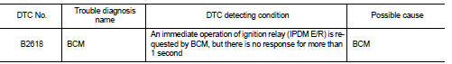
DTC DETECTION LOGIC
NOTE
:
тАв If DTC B2618 is displayed with DTC U1000, first perform the trouble diagnosis
for DTC U1000. Refer to
BCS-83, "DTC Logic".
тАв If DTC B2618 is displayed with DTC U1010, first perform the trouble diagnosis for DTC U1010. Refer to BCS-84, "DTC Logic".
DTC CONFIRMATION PROCEDURE
1.PERFORM DTC CONFIRMATION PROCEDURE
1. Turn ignition switch ON under the following conditions, and wait for 1 second or more.
CVT models
- Selector lever is in the P or N position
- Do not depress brake pedal
M/T models
- Do not depress clutch pedal
2. Check тАЬSelf-diagnosis resultтАЭ of BCM with CONSULT-III.
Is DTC detected? YES >> Go to PCS-100, "Diagnosis Procedure".
NO >> INSPECTION END
Diagnosis Procedure
1.INSPECTION START
1. Turn ignition switch ON.
2. Select тАЬSelf-diagnosis resultтАЭ of BCM with CONSULT-III.
3. Touch тАЬERASEтАЭ.
4. Perform DTC Confirmation Procedure.
See PCS-100, "DTC Logic".
Is the 1st trip DTC B2618 displayed again? YES >> Replace BCM. Refer to BCS-93, "Removal and Installation" NO >> INSPECTION END
 B2615 blower relay circuit
DTC Logic
DTC DETECTION LOGIC
DTC CONFIRMATION PROCEDURE
1.PERFORM DTC CONFIRMATION PROCEDURE
1. Turn ignition switch ON under the following conditions, and wait for 1
second or more.
CVT m ...
 B261A push-button ignition switch
DTC Logic
DTC DETECTION LOGIC
NOTE:
тАв If DTC B261A is displayed with DTC U1000, first perform the trouble diagnosis
for DTC U1000. Refer to
BCS-83, "DTC Logic".
тАв If DTC B261A is ...
Other materials:
Precaution for Supplemental Restraint System (SRS) "AIR BAG" and "SEAT BELT
PRE-TENSIONER"
The Supplemental Restraint System such as тАЬAIR BAGтАЭ and тАЬSEAT BELT PRE-TENSIONERтАЭ,
used along
with a front seat belt, helps to reduce the risk or severity of injury to the
driver and front passenger for certain
types of collision. Information necessary to service the system safely is
...
Wheel Alignment
HR16DE, K9K
Measure value under unladen*2 conditions.
*1: Since adjustment mechanism is not included, the value of the left and right
wheels (both wheels) must be
used as the standard value.
*2: Fuel, engine coolant and lubricant are full. Spare tire, jack, hand tools
and mats are in des ...
Hazard switch
Component Function Check
1.CHECK HAZARD SWITCH SIGNAL BY CONSULT-III
CONSULT-III DATA MONITOR
1. Turn the ignition switch ON.
2. Select тАЬHAZARD SWтАЭ of BCM (FLASHER) data monitor item.
3. With operating the hazard switch, check the monitor status.
Is the inspection result normal?
YES > ...
