Nissan Juke Service and Repair Manual : Hazard switch
Component Function Check
1.CHECK HAZARD SWITCH SIGNAL BY CONSULT-III
 CONSULT-III DATA MONITOR
1. Turn the ignition switch ON.
2. Select тАЬHAZARD SWтАЭ of BCM (FLASHER) data monitor item.
3. With operating the hazard switch, check the monitor status.
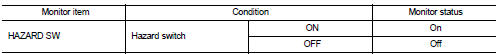
Is the inspection result normal? YES >> Hazard switch circuit is normal.
NO >> Refer to EXL-72, "Diagnosis Procedure".
Diagnosis Procedure
1.CHECK HAZARD SWITCH SIGNAL INPUT
1. Turn ignition switch OFF.
2. Disconnect hazard switch connector.
3. Check voltage between hazard switch connector and ground.
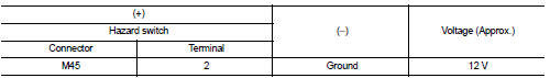
Is the inspection result normal? YES >> GO TO 4.
NO >> GO TO 2.
2.CHECK HAZARD SWITCH SIGNAL OPEN CIRCUIT
1. Disconnect BCM connector.
2. Check continuity between hazard switch harness connector and BCM harness connector.
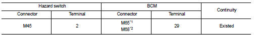
*1: Without Intelligent Key *2: With Intelligent Key
Is the inspection result normal? YES >> GO TO 3.
NO >> Repair or replace harness.
3.CHECK HAZARD SWITCH SIGNAL SHORT CIRCUIT
Check continuity between hazard switch harness connector and ground.
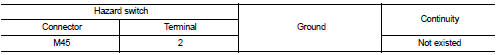
Is the inspection result normal?
YES >> Replace BCM. Refer to BCS-93, "Removal and Installation" (with Intelligent Key) or BCS-161, "Removal and Installation" (without Intelligent Key).
NO >> Repair or replace harness.
4.CHECK HAZARD SWITCH GROUND OPEN CIRCUIT
Check continuity between hazard switch harness connector and ground.
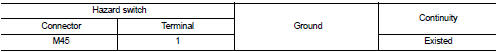
Is the inspection result normal? YES >> Replace hazard switch.
NO >> Repair or replace harness.
 Turn signal lamp circuit
Component Function Check
1.CHECK TURN SIGNAL LAMP
CONSULT-III ACTIVE TEST
1. Select тАЬFLASHERтАЭ of BCM (FLASHER) active test item.
2. With operating the test items, check that the turn signal la ...

Other materials:
Front fender
Exploded View
1. Front fender assembly
2. Front fender stiffener
: Vehicle front
Removal and Installation
REMOVAL
1. Remove front fillet molding. Refer to EXT-26, "FRONT FILLET MOLDING :
Removal and Installation".
2. Remove front bumper fascia assembly. Refer to EXT-13, "R ...
B1067, B1072 passenger air bag module
DTC Logic
DTC DETECTION LOGIC
DTC CONFIRMATION PROCEDURE
1.CHECK SELF-DIAG RESULT
With CONSULT-III
1. Turn ignition switch ON.
2. Perform тАЬSelf Diagnostic ResultтАЭ mode of тАЬAIR BAGтАЭ using CONSULT-III.
Without CONSULT-III
1. Turn ignition switch ON.
2. Check the air bag warning la ...
Diagnosis system (TCM)
CONSULT-III Function (TRANSMISSION)
CONSULT-III can display each diagnostic item using the diagnostic test modes
shown below.
FUNCTION
*: тАЬFunction TestтАЭ can be selected, but do not use it.
WORK SUPPORT MODE
Display Item List
Engine Brake Adjustment
тАЬENGINE BRAKE LEVELтАЭ
0: ...
