Nissan Juke Service and Repair Manual : Component parts
Component Parts Location
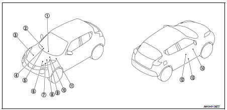
1. Remote keyless entry receiver Refer to DLK-361, "Component Parts Location" (With super lock) or DLK-492, "Component Parts Location" (Without super lock).
2. Combination meter Refer to MWI-4, "METER SYSTEM : Component Parts Location".
3. Stop lamp switch Refer to BRC-9, "Component Parts Location" (Without ESP) or BRC-97, "Component Parts Location" (With ESP).
4. NATS antenna amp. (Behind ignition switch)
5. Ignition switch
6. Transmission range switch
Refer to TM-131, "CVT CONTROL
SYSTEM : Component Parts Location"
(CVT: RE0F10A) or TM-314,
"CVT CONTROL SYSTEM : Component
Parts Location" (RE0F11A).
7. ECM Refer to EC-25, "ENGINE CONTROL SYSTEM : Component Parts Location" (MR16DDT), EC-455, "ENGINE CONTROL SYSTEM : Component Parts Location" (HR16DE) or EC-813, "Component Parts Location" (K9K).
8. IPDM E/R Refer to PCS-5, "Component Parts Location".
9. TCM Refer to TM-131, "CVT CONTROL SYSTEM : Component Parts Location" (CVT: RE0F10A) or TM-314, "CVT CONTROL SYSTEM : Component Parts Location" (RE0F11A).
10. ABS actuator and electric unit (control unit) Refer to BRC-9, "Component Parts Location" (Without ESP) or BRC-97, "Component Parts Location" (With ESP).
11. BCM Refer to BCS-6, "BODY CONTROL SYSTEM : Component Parts Location".
12. Front door lock assembly 13. Front door switch (driver side) 14. Power window main switch (door lock/unlock switch)
Component Description
BCM
BCM performs the ID verification between BCM and ECM when ignition switch is turned ON.
If the verification result is OK, ECM can start engine. If the verification result is NG, ECM cannot start engine.
IPDM E/R
Starter control relay is integrated in IPDM E/R and used for the engine starting system. Starter control relay is controlled by IPDM E/R while communicating with BCM and ECM. IPDM E/R sends the starter control relay status signal to ECM.
Door Switch
Door switch detects door open/close condition and then transmits ON/OFF signal to BCM.
Hood Switch
Hood switch detects that hood is open, and then transmits the signal to IPDM E/R. IPDM E/R transmits hood switch signal to BCM via CAN communication.
Ignition Key
The ID verification is performed between BCM and ignition key via NATS antenna amp. when ignition switch is turned ON. If an unregistered ID of ignition key is used, the operation of the starting engine is prohibited.
NATS Antenna Amp
The ID verification is performed between BCM and ignition key via NATS antenna amp. when ignition switch is turned ON. If an unregistered ID of ignition key is used, the operation of the starting engine is prohibited.
Remote Keyless Entry Receiver
Remote keyless entry receiver receives each button operation signal and electronic key ID signal from Keyfob, and then transmits the signal to BCM.
Security Indicator Lamp
Security indicator lamp is located on combination meter.
Security indicator lamp blinks when power supply position is in any position except the ON position to warn that Nissan Anti-Theft System (NATS) is on board.
Starter Control Relay
Starter control relay is integrated in IPDM E/R and used for the engine starting system. Starter control relay is controlled by IPDM E/R while communicating with BCM and ECM. IPDM E/R sends the starter control relay status signal to ECM.
Transmission Range Switch
Transmission range switch is integrated in CVT assembly to detect the selector lever position, and then transmits the P/N position signal to IPDM E/R.

 System
NISSAN anti-theft system
NISSAN ANTI-THEFT SYSTEM : System Diagram
NISSAN ANTI-THEFT SYSTEM : System Description
SYSTEM DESCRIPTION
Nissan Anti-Theft System (NATS) has the following immobilizer ...
Other materials:
Blower fan on signal
Component Function Check
1.CHECK BLOWER FAN ON SIGNAL
With CONSULT-III
1. Turn ignition switch ON.
2. Select ŌĆ£AIR CONDITIONERŌĆØ of ŌĆ£BCMŌĆØ using CONSULT-III.
3. Select ŌĆ£FAN ON SIGŌĆØ in ŌĆ£DATA MONITORŌĆØ mode.
4. Check blower fan ON signal when the fan control dial is operated.
Is t ...
Nats antenna AMP
Removal and Installation
REMOVAL
1. Remove the cluster lid A. Refer to IP-13, "Removal and Installation".
2. Remove the NATS antenna amp.
1. Disengage the NATS antenna amp. (1) fixing pawls using
minus driver etc.
2. Pull NATS antenna amp. to remove it from push-button ignition
sw ...
Driving on snow or ice
WARNING
ŌĆó Wet ice (328F, 08C and freezing rain), very cold snow or ice can be slick
and very hard to drive on. The vehicle will have much less traction or ŌĆ£gripŌĆØ under
these conditions. Try to avoid driving on wet ice until the road is salted or sanded.
ŌĆó Whatever the condition, drive ...
