Nissan Juke Service and Repair Manual : System
NISSAN anti-theft system
NISSAN ANTI-THEFT SYSTEM : System Diagram
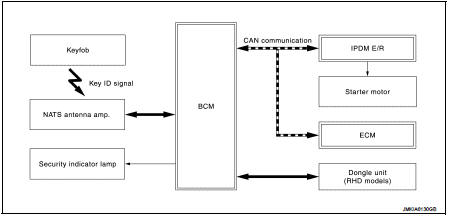
NISSAN ANTI-THEFT SYSTEM : System Description
SYSTEM DESCRIPTION
Nissan Anti-Theft System (NATS) has the following immobilizer functions: ŌĆó NATS shows high anti-theft performance to prevent engine from starting by anyone other than the owner who has the registered ignition key.
ŌĆó The ignition key has NATS ID and only ignition key which has the same ID as the ID registered in BCM and ECM can start engine. This makes high anti-theft performance to prevent the vehicle from being stolen using a copied ignition key.
ŌĆó Security indicator lamp always blinks when ignition switch is in any position other than the ON position. Therefore, NATS warns outsiders that the vehicle is equipped with the anti-theft system.
ŌĆó If the system detects a malfunction, security indicator lamp illuminates when ignition switch is turned ON.
ŌĆó If the owner requires, ignition key ID can be registered for up to 5 keys.
ŌĆó During trouble diagnosis, when additional ignition key is needed, or when the following components are replaced, the ID registration is required. For the registration procedure, refer to CONSULT-III Operation Manual NATS-IVIS/NVIS.
- BCM
- Ignition key
ŌĆó Possible symptom of NATS malfunction is ŌĆ£Engine cannot startŌĆØ. The engine also
can not be started
because of other than the NATS malfunction, so start the trouble diagnosis
according to SEC-187, "Work
Flow".
ŌĆó If ECM other than Genuine NISSAN parts is installed, the engine cannot be started. For ECM replacement procedure, refer to EC-447, "Removal and Installation" (MR16DDT), or EC-805, "Removal and Installation" (HR16DE).
PRECAUTIONS FOR KEY REGISTRATION
ŌĆó Refer to CONSULT-III Operation Manual NATS-IVIS/NVIS, for the actual procedure of NATS ID registration.
ŌĆó The NATS ID registration is the procedure that registers the ID stored into the ignition key (transponder is integrated) to BCM.
SECURITY INDICATOR LAMP
ŌĆó Security indicator lamp is located on combination meter and warns that the vehicle is equipped with NATS.
ŌĆó Security indicator lamp always blinks, when the ignition switch is in any position other than the ON position.
ŌĆó Security indicator lamp turns OFF when the ignition switch is in ON position.
OPERATION WHEN IGNITION KEY IS INSERTED INTO IGNITION KEY CYLINDER
1. When ignition switch is turned ON, BCM activates NATS antenna amp. to start NATS ID verification with the ignition key (transponder is integrated).
2. BCM receives the NATS ID signal from ignition key via NATS antenna amp. and verifies it with the registered ID.
3. When the NATS ID verification result is OK, BCM performs the ID verification between BCM and ECM.
4. When the verification result is OK, BCM sends the verification OK signal to ECM, and then ECM can start the engine.
5. When the ignition switch is turned to the START position, BCM sends the starter request signal to IPDM E/ R.
Vehicle security system
VEHICLE SECURITY SYSTEM : System Diagram
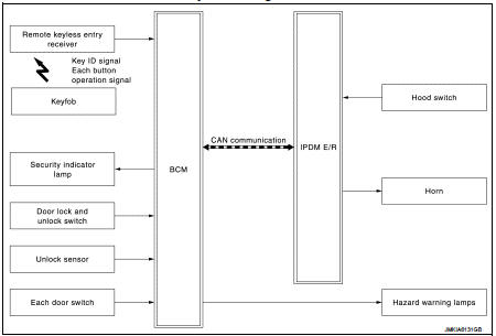
VEHICLE SECURITY SYSTEM : System Description
ŌĆó The vehicle security system has two alarm functions (theft warning alarm and panic alarm), and reduces the possibility of a theft or mischief by activating horns and hazard warning lamps intermittently.
ŌĆó The panic alarm does not start when the theft warning alarm is activating, and the panic alarm stops when the theft warning alarm is activated.
The priority of the functions are as per the following.

THEFT WARNING ALARM
ŌĆó The theft warning alarm function activates horns and hazard warning lamps intermittently when BCM detects that any door or hood is opened by unauthorized means, while the system is in the ARMED state.
ŌĆó Security indicator lamp on combination meter always blinks when ignition switch is any position other than ON. Security indicator lamp blinking warns that the vehicle is equipped with a vehicle security system.
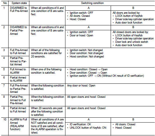
Operation Flow
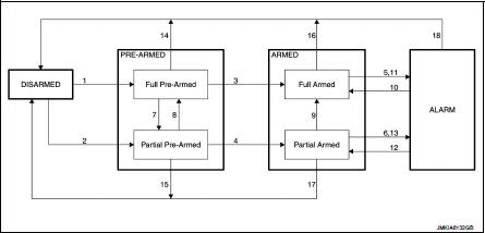
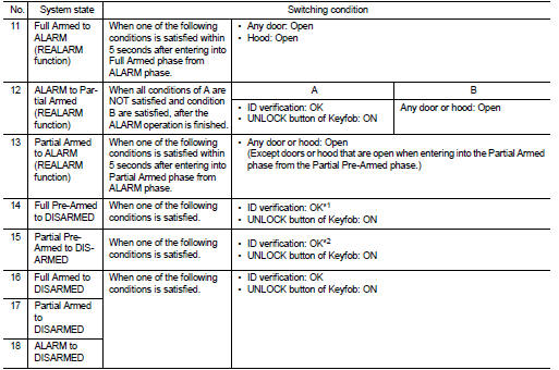
ŌĆó *1: If ignition switch is turned ON without OK result of ID verification, the system status changes to the ALARM phase via the Partial Pre-Armed and Partial Armed phases.
ŌĆó *2: If ignition switch is turned ON without OK result of ID verification, the system status changes to the ALARM phase via the Partial Armed phases.
NOTE
:
ŌĆó To lock/unlock all doors by operating remote controller button of keyfob, the
keyfob must be within the detection area of remote keyless
entry receiver. For details, refer to DLK-366, "REMOTE KEYLESS ENTRY FUNCTION :
System Description" (Models with super
lock), or DLK-497, "System Description" (Models without super lock).
DISARMED Phase
The vehicle security system is not set in the DISARMED phase. Security indicator
lamp blinks every 2.4 seconds.
When the vehicle security system is reset, each phase switches to the DISARMED phase directly.
PRE-ARMED Phase
The PRE-ARMED phase is the transient state between the DISARMED phase and the
ARMED phase. This
phase is maintained for 20 seconds, so that the owner can reset the setting due
to a mis-operation. This phase
switches to the ARMED phase when vehicle conditions are not changed for 20
seconds.
There are two type of phase (Full Pre-Armed and Partial Pre-Armed).
ŌĆó Full Pre-Armed phase
Vehicle security system enters into this phase when all doors are closed.
Security indicator lamp blinks at 8
Hz while being in this phase. If any door is opened during this phase, the
system status changes to Partial
Pre-Armed phase.
To reset this phase, refer to the switching condition of No. 14 in the table above.
ŌĆó Partial Pre-Armed phase Vehicle security system enters into this phase when one or more doors are open. Security indicator lamp does not blink while being in this phase. If all doors are closed during this phase, the system status changes to Full Pre-Armed phase.
To reset this phase, refer to the switching condition of No. 15 in the table above.
ARMED Phase
The vehicle security system is set, and BCM monitors all necessary inputs. If
any door or hood is opened by
unauthorized means, vehicle security system switches to the ALARM phase.
Security indicator lamp blinks
every 2.4 seconds.
There are two type of phase (Full Armed and Partial Armed).
ŌĆó Full Armed phase
Vehicle security system enters into this phase from Full Pre-Armed phase.
To reset this phase, refer to the switching condition of No. 16 in the table above.
ŌĆó Partial Armed phase
Vehicle security system enters into this phase from Partial Pre-Armed phase. If
all doors are closed during
being this phase, the system status changes to Full Armed phase.
To reset this phase, refer to the switching condition of No. 17 in the table above.
ALARM Phase
BCM transmits ŌĆ£Theft Warning Horn RequestŌĆØ signal intermittently to IPDM E/R via
CAN communication, and
blinks hazard warning lamps. In this phase, horns and hazard warning lamps are
activated intermittently for
approximately 27.5 seconds to warn that the vehicle is accessed by unauthorized
means.
Horns are sounding at 2.5 Hz, and hazard warning lamps blinks at 1.42 Hz.
To cancel the ALARM operation, refer to the switching condition of No. 18 in the table above.
NOTE
:
If a battery terminal is disconnected during the ALARM phase, theft warning
alarm stops. But when the battery
terminal is reconnected, theft warning alarm is activated again.
REALARM Phase
When ALARM phase is maintained for 27.5 seconds without any cancel operation,
the system status returns
to the ARMED phase. At this time, if BCM still detects unauthorized access to
the vehicle, the system is
switched to the ALARM phase again. This REALARM operation is carried out a
maximum of 8 times.
PANIC ALARM
Panic alarm is not applied to this models.
 Component parts
Component Parts Location
1. Remote keyless entry receiver
Refer to DLK-361,
"Component Parts Location" (With
super lock) or DLK-492,
"Component Parts Location" (Without
sup ...
 Diagnosis system (BCM)
Common item
COMMON ITEM : CONSULT-III Function (BCM - COMMON ITEM)
APPLICATION ITEM
CONSULT-III performs the following functions via CAN communication with BCM.
SYSTEM APPLICATION
BCM can perfo ...
Other materials:
Cleanliness
Cleanliness
RISKS ASSOCIATED WITH CONTAMINATION
The high pressure direct injection system is highly sensitive to
contamination. The risks associated with contamination
are:
ŌĆó damage to or destruction of the high pressure injection system,
ŌĆó components jamming,
ŌĆó components losing seal ...
System (intelligent key system)
Intelligent key system : System Diagram
Intelligent key system : System Description
ŌĆó The Intelligent Key system is a system that makes it possible to lock and
unlock the door locks (door lock/
unlock function) by carrying the Intelligent Key, which operates based on the
results of electr ...
Rear shock absorber
Exploded View
1. Suspension arm
2. Shock absorber
3. Bound bumper
4. Bound bumper cover
5. Washer
6. Bushing
7. Distance tube
8. Piston rod lock nut
9. Cap
: Vehicle front
: Always replace after every
disassembly.
: N┬Ęm (kg-m, ft-lb)
Removal and Installation
REMOVAL
1. Remov ...
