Nissan Juke Service and Repair Manual : Rear shock absorber
Exploded View
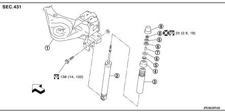
1. Suspension arm
2. Shock absorber
3. Bound bumper
4. Bound bumper cover
5. Washer
6. Bushing
7. Distance tube
8. Piston rod lock nut
9. Cap
 : Vehicle front
 : Always replace after every
disassembly.
 : N┬Ęm (kg-m, ft-lb)
Removal and Installation
REMOVAL
1. Remove tires. Refer to WT-7, "Removal and Installation".
2. Set suitable jack under suspension arm.
CAUTION:
ŌĆó Never damage the suspension arm with a jack.
ŌĆó Check the stable condition when using a jack.
3. Remove shock absorber mounting bolt and nut (lower side).
4. Remove shock absorber mask. Refer to INT-29, "Exploded View".
5. Remove cap.
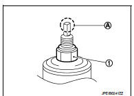
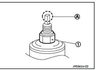
6. Remove piston rod lock nut (1), and then remove washer and bushing.
NOTE
:
To loosen piston rod lock nut, fix the tip (A) of the piston rod.
7. Remove shock absorber assembly.
8. Remove bushing, distance tube, bound bumper cover, and bound bumper from shock absorber.
9. Perform inspection after removal. Refer to RSU-24, "Inspection".
INSTALLATION
Note the following, and install in the reverse order of removal.
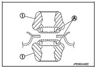
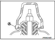
ŌĆó To install bushings (1), securely insert protrusion (A) into the hole on the vehicle body side.
ŌĆó Install washer (1) in the direction shown in the figure.
: Bushing side
ŌĆó Perform final tightening of bolts and nuts at the shock absorber lower side (rubber bussing), under unladen conditions with tires on level ground.
ŌĆó Hold a head (A) of shock absorber piston rod not to have it rotate, then tighten the piston rod lock nut (1) to the specified torque.
CAUTION:
Never reuse piston rod lock nut.
ŌĆó When installing the cap, securely engage the cap groove (A) with the flange on the vehicle side.
ŌĆó Perform inspection after installation. Refer to RSU-24, "Inspection".
ŌĆó After replacing the shock absorber, always follow the disposal procedure to discard the shock absorber. Refer to RSU-24, "Inspection".
Inspection
INSPECTION AFTER REMOVAL
Shock Absorber
Check the following items, and replace the part if necessary.
ŌĆó Shock absorber for deformation, cracks, and other damage.
ŌĆó Piston rod for damage, uneven wear, and distortion.
ŌĆó Oil leakage
Bound Bumper, Bushing Check for cracks and damage. Replace it if necessary.
Washer, Bound Bumper Cover, Distance Tube ŌĆó Check for cracks and damage. Replace it if necessary.
INSPECTION AFTER INSTALLATION
Check wheel alignment. Refer to RSU-20, "Inspection".
Disposal
1. Set shock absorber horizontally to the ground with the piston rod fully extracted.
2. Drill 2 ŌĆō 3 mm (0.08 ŌĆō 0.12 in) hole at the position (
 ) from top
as shown in the figure to release gas gradually.
CAUTION:
ŌĆó Wear eye protection (safety glass).
ŌĆó Wear gloves.
ŌĆó Be careful with metal chips or oil blown out by the compressed gas.
NOTE:
ŌĆó Drill vertically in this direction (
 ).
).
ŌĆó Directly to the outer tube avoiding brackets.
ŌĆó The gas is clear, colorless, odorless, and harmless.
A : 20 ŌĆō 30 mm (0.79 ŌĆō 1.18 in)
3. Position the drilled hole downward and drain oil by moving the piston rod several times.
CAUTION:
Dispose of drained oil according to the law and local regulations.

 Coil spring
Exploded View
1. Upper rubber seat
2. Coil spring
3. Lower rubber seat
4. Suspension arm
: Vehicle front
Removal and Installation
REMOVAL
1. Remove tires. Refer to WT-7, "Removal and ...
Other materials:
Diagnosis system (IPDM E/R)
With intelligent key
WITH INTELLIGENT KEY : Diagnosis Description
AUTO ACTIVE TEST
Description
In auto active test mode, the IPDM E/R sends a drive signal to the following
systems to check their operation.
ŌĆó Oil pressure warning lamp (only for K9K engine models)
ŌĆó Rear window defogger
...
Door cable
Exploded View
LEFT SIDE
1. A/C unit assembly
2. Intake door lever
3. Intake door link
4. Intake door cable
5. Air mix door cable
6. Upper air mix door rod
7. Upper air mix door lever
8. Lower air mix door lever
9. Lower air mix door rod
10. Air mix door link
A. To A/C control
RI ...
P0327, P0328 KS
DTC Logic
DTC DETECTION LOGIC
DTC CONFIRMATION PROCEDURE
1.PRECONDITIONING
If DTC Confirmation Procedure has been previously conducted, always turn
ignition switch OFF and wait at
least 10 seconds before conducting the next test.
TESTING CONDITION:
Before performing the following proced ...
