Nissan Juke Service and Repair Manual : Coil spring
Exploded View
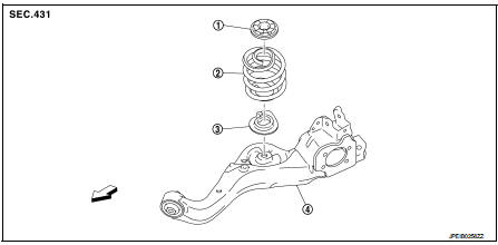
1. Upper rubber seat
2. Coil spring
3. Lower rubber seat
4. Suspension arm
 : Vehicle front
Removal and Installation
REMOVAL
1. Remove tires. Refer to WT-7, "Removal and Installation".
2. Remove wheel sensor and sensor harness. Refer to BRC-86, "REAR WHEEL SENSOR : Removal and Installation" (Without ESP), BRC-227, "REAR WHEEL SENSOR : Removal and Installation" (With ESP).
3. Set jack under suspension arm.
CAUTION:
• Never damage the suspension arm with a jack.
• Check the stable condition when using a jack.
4. Separate rear shock absorber lower side form suspension arm. Refer to RSU-8, "Removal and Installation".
5. Separate upper link from suspension arm.
6. Slowly lower jack, then remove upper rubber seat, coil spring and lower rubber seat from suspension arm.
CAUTION:
Operate while checking that jack supporting status is stable.
7. Perform inspection after removal. Refer to RSU-27, "Inspection" INSTALLATION
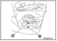
Note the following, and install in the reverse order of removal.
• Install the lower rubber seat a projection (A) is attached as suspension arm mounting hole (B).
• Match up lower rubber seat indentions and suspension arm grooves and attach.
• Perform inspection after installation. Refer to RSU-27, "Inspection".
Inspection
INSPECTION AFTER REMOVAL
Check lubber seat and coil spring for deformation, crack, and damage. Replace it if necessary.
INSPECTION AFTER INSTALLATION
1. Check wheel sensor harness for proper connection. Refer toBRC-85, "REAR WHEEL SENSOR : Exploded View" (Without ESP), BRC-225, "REAR WHEEL SENSOR : Exploded View" (With ESP).
2. Check wheel alignment. Refer to RSU-20, "Inspection".
 Rear shock absorber
Exploded View
1. Suspension arm
2. Shock absorber
3. Bound bumper
4. Bound bumper cover
5. Washer
6. Bushing
7. Distance tube
8. Piston rod lock nut
9. Cap
: Vehicle front
: Always r ...
 Suspension arm
Exploded View
1. Rear suspension member
2. Adjusting bolt
3. Upper link
4. Eccentric disk
5. Lower link
6. Suspension arm bracket
7. Suspension arm
: Vehicle front
: Always replace afte ...
Other materials:
Precaution for Supplemental Restraint System (SRS) "AIR BAG" and "SEAT BELT
PRE-TENSIONER"
The Supplemental Restraint System such as “AIR BAG” and “SEAT BELT PRE-TENSIONER”,
used along
with a front seat belt, helps to reduce the risk or severity of injury to the
driver and front passenger for certain
types of collision. Information necessary to service the system safely is
...
P1572 ASCD brake switch
DTC Logic
DTC DETECTION LOGIC
NOTE:
• If DTC P1572 is displayed with DTC P0605, first perform the trouble diagnosis
for DTC P0605. Refer
to EC-302, "DTC Logic".
• This self-diagnosis has the one trip detection logic. When malfunction A is
detected, DTC is not
stored in ECM me ...
C1166, C1167 SV system
DTC Logic
DTC DETECTION LOGIC
DTC CONFIRMATION PROCEDURE
1.PRECONDITIONING
If “DTC CONFIRMATION PROCEDURE” has been previously conducted, always turn
ignition switch OFF and
wait at least 10 seconds before conducting the next test.
>> GO TO 2.
2.CHECK DTC DETECTION
With CON ...
