Nissan Juke Service and Repair Manual : Removal and installation
ALTERNATOR
HR16DE
HR16DE : Exploded View
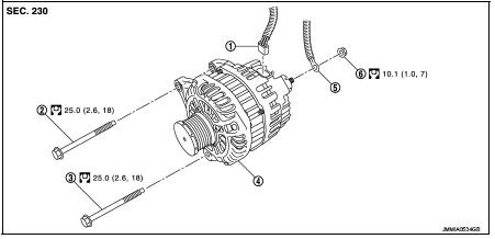
REMOVAL
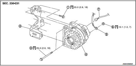
1. Alternator bracket mounting bolt
2. Alternator bracket
3. Alternator mounting bolt
4. Alternator
5. “B” terminal harness
6. “B” terminal nut
7. Alternator connector
 : N·m (kg-m, ft-lb)
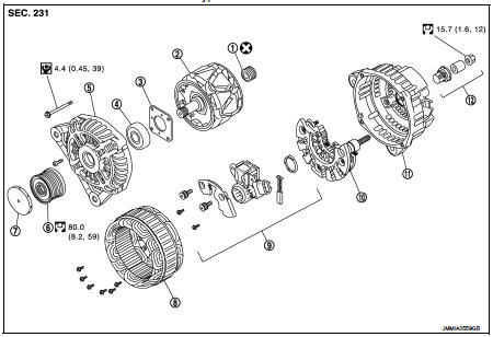
DISASSEMBLY
Type: A002TJ1291ZE
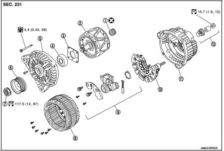
1. Rear bearing
2. Rotor assembly
3. Retainer
4. Front bearing
5. Front bracket assembly
6. Pulley
7. Pulley nut
8. Stator assembly
9. IC voltage regulator assembly
10. Diode assembly
11. Rear bracket assembly
12. Terminal set
 :
:
Do not reuse
 : N·m (kg-m, in-lb)
 : N·m (kg-m, ft-lb)
HR16DE : Removal and Installation
REMOVAL
1. Disconnect the battery cable from the negative terminal. Refer to PG-124, "Removal and Installation".
2. Remove radiator reservoir tank. Refer to CO-17, "Exploded View".
3. Remove drive belt. Refer to EM-155, "Removal and Installation".
4. Disconnect alternator connector.
5. Remove “B” terminal nut and disconnect “B” terminal harness.
6. Remove alternator mounting bolts.
7. Remove alternator upward from the vehicle.
INSTALLATION
Note the following items, and then install in the reverse order of removal.
CAUTION:
• Temporarily tighten the alternator bolts in order from the lower to the upper,
and then tighten them in
order from the upper to the lower.
• For the alternator, the front side (pulley side) surface is the reference surface. Fit the reference surface to the alternator mounting part, and then tighten the bolts.
• Be careful to tighten “B” terminal nut carefully.
• Install alternator, and check tension of belt. Refer to EM-154, "Checking".
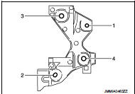
NOTE:
Tighten mounting bolts according to the following procedures for installing alternator bracket.
1. Temporarily tighten mounting bolt (1).
2. Temporarily tighten mounting bolt (2).
3. Tighten mounting bolts in numerical order as shown in the figure.
HR16DE : Disassembly and Assembly
DISASSEMBLY
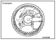
Rear Cover
NOTE
:
Rear cover may be hard to remove because a ring is used to lock
outer race of rear bearing. To facilitate removal of rear cover, heat
only the bearing box section until the temperature increases to
approximately 30°C (86°F) with a soldering iron (200W capacity).
CAUTION:
Never use a heat gun, as if can damage diode assembly.
ASSEMBLY
Rear Bearing
CAUTION:
• Never reuse rear bearing. Replace with a new one.
• Never lubricate rear bearing outer race.
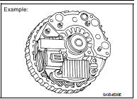
Rear Cover Installation 1. Fit brush assembly, diode assembly, regulator assembly and stato
2. Push brushes up with fingers and install them to rotor.
NOTE
:
Take care not damage slip ring sliding surface.
HR16DE : Inspection
INSPECTION
Rotor Check
1. Resistance test
Resistance : Refer to SDS CHG-35, "Alternator".
• Replace the rotor if the measurement value is outside of the specified range.
2. Insulator test
• Replace the rotor if continuity exists.
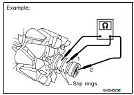
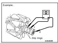
3. Check slip ring for wear.
Slip ring minimum outer diameter : Refer to SDS CHG-35, "Alternator".
• Replace the rotor if the measurement value is outside of the specified range.
Brush Check
1. Check smooth movement of brush.
• Check brush holder and clean if it is not smooth.
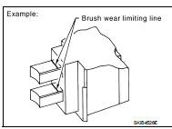
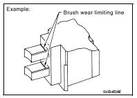
2. Check brush for wear.
• Replace brush if it is worn down to the limit line.
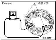
Stator Check
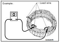
1. Continuity test
• Replace the stator if continuity does not exist.
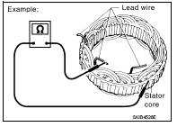
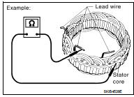
2. Ground test
• Replace the stator if continuity exists.
MR16DDT
MR16DDT : Exploded View
REMOVAL
1. Alternator connector
2. Alternator mounting bolt (upper)
3. Alternator mounting bolt (lower)
4. Alternator
5. “B” terminal harness
6. “B” terminal nut
 : N·m (kg-m, ft-lb)
DISASSEMBLY
Type: A002TJ1381
1. Rear bearing
2. Rotor assembly
3. Retainer
4. Front bearing
5. Front bracket assembly
6. Pulley
7. Pulley cap
8. Stator assembly
9. IC voltage regulator assembly
10. Diode assembly
11. Rear bracket assembly
12. Terminal set
 : Do not reuse
 : N·m (kg-m, in-lb)
: N·m (kg-m, ft-lb)
: N·m (kg-m, in-lb)
: N·m (kg-m, ft-lb)
MR16DDT : Removal and Installation
REMOVAL
1. Disconnect the battery cable from the negative terminal. Refer to PG-124, "Removal and Installation".
2. Remove charge air cooler. Refer to EM-31, "Removal and Installation".
3. Remove drive belt. Refer to EM-20, "Removal and Installation".
4. Disconnect alternator connector.
5. Remove “B” terminal nut and disconnect “B” terminal harness.
6. Remove alternator mounting bolt (upper).
7. Completely loosen alternator mounting bolt (lower), and pull it out until the bolt head is in contact with the side member. And then, remove the alternator by pulling it forward.
NOTE
:
The alternator can be removed together with the bolts by pulling it forward and
using the thermostat housing
bolt hole cutout.
8. Remove alternator forward from the vehicle.
INSTALLATION
Note the following items, and then install in the reverse order of removal.
CAUTION:
• Temporarily tighten the alternator bolts in order from the lower to the upper,
and then tighten them in
order from the upper to the lower
. • For the alternator, the front side (pulley side) surface is the reference surface. Fit the reference surface to the alternator mounting part, and then tighten the bolts.
• Be careful to tighten “B” terminal nut carefully.
• Install alternator, and check tension of belt. Refer to EM-20, "Checking".
• For this model, the power generation voltage variable control system that controls the power generation voltage of the alternator has been adopted. Therefore, the power generation voltage variable control system operation inspection should be performed after replacing the alternator, and then make sure that the system operates normally. Refer to CHG-18, "Inspection Procedure".
MR16DDT : Disassembly and Assembly
DISASSEMBLY
Rear Cover
NOTE
:
Rear cover may be hard to remove because a ring is used to lock
outer race of rear bearing. To facilitate removal of rear cover, heat
only the bearing box section until the temperature increases to
approximately 30°C (86°F) with a soldering iron (200W capacity).
CAUTION:
Never use a heat gun, as if can damage diode assembly.
Front Cover
1. Set rotor to the vise.
CAUTION:
• Be careful not to damage the rotor.
• Use copper plate or thick cloth for rotor in the vise.
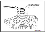
2. Remove pulley cap, using suitable tool.
![3. Remove alternator pulley, using alternator pulley adaptor [SST].](images/books/335/59/7.html72.gif)
3. Remove alternator pulley, using alternator pulley adaptor [SST].
ASSEMBLY
Rear Bearing
CAUTION:
• Never reuse rear bearing. Replace with a new one.
• Never lubricate rear bearing outer race.
Rear Cover Installation
1. Fit brush assembly, diode assembly, regulator assembly and stator assembly.
2. Push brushed up with fingers and install them to rotor.
NOTE
:
Take care not damage slip ring sliding surface.
MR16DDT : Inspection
INSPECTION AFTER DISASSEMBLY
Rotor Check
1. Resistance test
Resistance : Refer to SDS CHG-35, "Alternator".
• Replace the rotor if the measurement value is outside of the specified range.
2. Insulator test
• Replace the rotor if continuity exists.
3. Check slip ring for wear.
Slip ring minimum outer diameter : Refer to SDS CHG-35, "Alternator".
• Replace the rotor if the measurement value is outside of the specified range.
Brush Check
1. Check smooth movement of brush.
• Check brush holder and clean if it is not smooth.
2. Check brush for wear.
• Replace brush if it is worn down to the limit line.
Stator Check
1. Continuity test
• Replace the stator if continuity does not exist.
2. Ground test
• Replace the stator if continuity exists.
 Symptom diagnosis
CHARGING SYSTEM
Symptom Table
...
 Service data and specifications (SDS)
Alternator
*: Adjustment range of power generation voltage variable control is 11.4 −
15.6 V. ...
Other materials:
Precaution for Power Generation Voltage Variable Control System
CAUTION:
For thailand model, the battery current sensor that is installed to the battery
cable at the negative terminal
measures the charging/discharging current of the battery, and performs various
controls. If the
electrical component or the ground wire is connected directly to the battery ...
Vehicle information
Identification information
Japan production models
JAPAN PRODUCTION MODELS : Model Variation
Model variation code (Prefix and suffix designations)
JAPAN PRODUCTION MODELS : Information About Identification or Model Code
IDENTIFICATION NUMBER
1. Air conditioner specification label
2. Ve ...
C1109 power and ground system
DTC Logic
DTC DETECTION LOGIC
DTC CONFIRMATION PROCEDURE
1.PRECONDITIONING
If “DTC CONFIRMATION PROCEDURE” has been previously conducted, always turn
ignition switch OFF and
wait at least 10 seconds before conducting the next test.
>> GO TO 2.
2.CHECK DTC DETECTION
With CON ...
