Nissan Juke Service and Repair Manual : Suspension arm
Exploded View
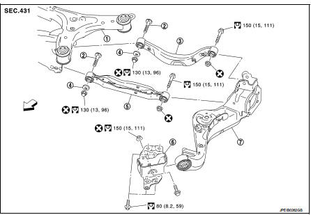
1. Rear suspension member
2. Adjusting bolt
3. Upper link
4. Eccentric disk
5. Lower link
6. Suspension arm bracket
7. Suspension arm
 : Vehicle front
 : Always replace after every
disassembly.
 : N·m (kg-m, ft-lb)
Removal and Installation
REMOVAL
1. Remove tires. Refer to WT-7, "Removal and Installation".
2. Drain brake fluid. Refer to BR-12, "Draining" (LHD), BR-80, "Draining" (RHD).
3. Remove wheel sensor and sensor harness. Refer to BRC-86, "REAR WHEEL SENSOR : Removal and Installation" (Without ESP), BRC-227, "REAR WHEEL SENSOR : Removal and Installation" (With ESP).
4. Remove caliper assembly. Refer to BR-65, "BRAKE CALIPER ASSEMBLY : Removal and Installation" (LHD), BR-131, "BRAKE CALIPER ASSEMBLY : Removal and Installation" (RHD).
5. Remove disc rotor. Refer to RAX-14, "Removal and Installation".
6. Remove parking brake cable mounting bolt. Refer to PB-5, "Removal and Installation".
7. Separate the brake tube from the brake hose, and remove lock plate. Refer to BR-30, "REAR : Exploded View" (LHD), BR-97, "REAR : Exploded View" (RHD).
8. Remove wheel hub assembly. Refer to RAX-14, "Removal and Installation".
9. Remove parking brake shoe and back plate. Refer to RAX-14, "Removal and Installation".
10. Set jack under suspension arm.
CAUTION
:
• Never damage the suspension arm with a jack.
• Check the stable condition when using a jack.
11. Remove stabilizer link. Refer to RSU-34, "Removal and Installation".
12. Remove upper link from suspension arm. Refer to RSU-32, "Removal and Installation".
13. Remove lower link from suspension arm. Refer to RSU-30, "Removal and Installation".
14. Remove coil spring from suspension arm. Refer to RSU-26, "Removal and Installation".
15. Remove suspension arm bracket from vehicle.
16. Remove suspension arm from suspension arm bracket.
17. Perform inspection after removal. Refer to RSU-29, "Inspection".
INSTALLATION
Note the following, and install in the reverse order of removal.
• Perform final tightening of rear suspension member installation position (rubber bussing), under unladen conditions with tires on level ground.
• Never reuse suspension arm mounting nut.
• Perform inspection after installation. Refer to RSU-29, "Inspection".
Inspection
INSPECTION AFTER REMOVAL
Check suspension arm and bushing for deformation, cracks or damage. Replace it if necessary.
INSPECTION AFTER INSTALLATION
1. Check wheel sensor harness for proper connection. Refer toBRC-85, "REAR WHEEL SENSOR : Exploded View" (Without ESP), BRC-225, "REAR WHEEL SENSOR : Exploded View" (With ESP).
2. Adjust parking brake operation (stroke). Refer toPB-2, "Inspection and Adjustment".
3. Check wheel alignment. Refer to RSU-20, "Inspection".
4. Adjust neutral position of steering angle sensor. Refer to BRC-149, "Work Procedure". (With ESP)
 Coil spring
Exploded View
1. Upper rubber seat
2. Coil spring
3. Lower rubber seat
4. Suspension arm
: Vehicle front
Removal and Installation
REMOVAL
1. Remove tires. Refer to WT-7, "Removal and ...
 Lower link
Exploded View
1. Rear suspension member
2. Adjusting bolt
3. Upper link
4. Eccentric disk
5. Lower link
6. Suspension arm bracket
7. Suspension arm
: Vehicle front
: Always replace afte ...
Other materials:
Precautions For Refrigerant System Service
GENERAL REFRIGERANT PRECAUTION
WARNING:
• Never breathe A/C refrigerant and lubricant vapor or mist. Exposure may
irritate eyes, nose and
throat. Use only approved recovery/recycling equipment to discharge HFC-134a
(R-134a) refrigerant.
Ventilate work area before resuming service if acci ...
P0850 PNP switch
Description
When the selector lever position is P or N (CVT), Neutral position (M/T),
park/neutral position (PNP) signal is
ON.
DTC Logic
DTC DETECTION LOGIC
DTC CONFIRMATION PROCEDURE
1.INSPECTION START
Do you have CONSULT-III?
Do you have CONSULT-III?
YES >> GO TO 2.
NO >& ...
Removal and Installation
REMOVAL
1. Remove engine assembly. Refer to EM-55, "2WD : Exploded View" (2WD) ,
EM-59, "4WD : Exploded
View" (4WD).
2. Remove oil pan (lower). Refer to EM-41, "Removal and Installation".
3. Remove front cover, and other related parts. Refer to EM-67, "Explod ...
