Nissan Juke Service and Repair Manual : Electrical load signal
Description
The electrical load signal (Headlamp switch signal, rear window defogger switch signal, etc.) is transferred to ECM through the CAN communication line.
Component Function Check
1.CHECK REAR WINDOW DEFOGGER SWITCH FUNCTION
1. Turn ignition switch ON.
2. Select ÔÇťDATA MONITORÔÇŁ mode with CONSULT-III.
3. Select ÔÇťLOAD SIGNALÔÇŁ and check indication under the following conditions.
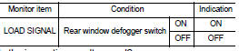
Is the inspection result normal? YES >> GO TO 2.
NO >> Go to EC-776, "Diagnosis Procedure".
2.CHECK LIGHTING SWITCH FUNCTION
Check ÔÇťLOAD SIGNALÔÇŁ indication under the following conditions.
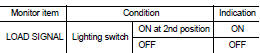
Is the inspection result normal? YES >> GO TO 3.
NO >> Go to EC-776, "Diagnosis Procedure".
3.CHECK HEATER FAN CONTROL SWITCH FUNCTION
Select ÔÇťHEATER FAN SWÔÇŁ and check indication under the following conditions.
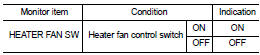
Is the inspection result normal? YES >> INSPECTION END
NO >> Go to EC-776, "Diagnosis Procedure".
Diagnosis Procedure
1.INSPECTION START
Confirm the malfunctioning circuit (rear window defogger, headlamp or heater fan). Refer to EC-776, "Component Function Check".
Which circuit is related to the incident? Rear window defogger>>GO TO 2 Headlamp>>GO TO 3.
Heater fan>>GO TO 4.
2.CHECK REAR WINDOW DEFOGGER SYSTEM
Perform trouble diagnosis of rear window defogger system. Refer to DEF-25, "Work Flow".
>> INSPECTION END
3.CHECK HEADLAMP SYSTEM
Perform trouble diagnosis of headlamp system. Refer to EXL-43, "Work Flow".
>> INSPECTION END
4.CHECK AIR CONDITIONING SYSTEM
Perform trouble diagnosis of air conditioning system. Check type of air conditioning system HAC-10, "Information" and refer to the follows.
ÔÇó TYPE1: HAC-44, "Work Flow" ÔÇó TYPE2: HAC-135, "Work Flow" ÔÇó TYPE3: HAC-216, "Work Flow" ÔÇó TYPE4: HAC-271, "Work Flow" ÔÇó TYPE5: HAC-322, "Work Flow"
>> INSPECTION END
 Cooling fan
Component Function Check
1.CHECK COOLING FAN FUNCTION
With CONSULT-III
1. Turn ignition switch ON.
2. Perform ÔÇťCOOLING FANÔÇŁ in ÔÇťACTIVE TESTÔÇŁ mode with CONSULT-III.
3. Touch ÔÇťLOWÔÇŁ and ...
 Fuel injector
Component Function Check
1.INSPECTION START
Turn ignition switch to START.
Is any cylinder ignited?
YES >> GO TO 2.
NO >> Go to EC-778, "Diagnosis Procedure".
2.CHECK ...
Other materials:
Speaker Adaptation (SA) mode
Speaker Adaptation allows up to two out-of dialect users to train the system
to improve recognition accuracy. By repeating a number of commands, the users can
create a voice model of their own voice that is stored in the system.
The system is capable of storing a different speaker adaptation mo ...
Camshaft
*: Total indicator readin
VALVE LIFTER
VALVE CLEARANCE
*: Approximately 80┬░C (176┬░F)
AVAILABLE VALVE LIFTER
...
U1010 control unit (can)
Description
CAN (Controller Area Network) is a serial communication line for real time
application. It is an on-vehicle multiplex
communication line with high data communication speed and excellent error
detection ability. Many electronic
control units are equipped onto a vehicle, and each co ...
