Nissan Juke Service and Repair Manual : Fuel injector
Component Function Check
1.INSPECTION START
Turn ignition switch to START.
Is any cylinder ignited? YES >> GO TO 2.
NO >> Go to EC-778, "Diagnosis Procedure".
2.CHECK FUEL INJECTOR FUNCTION
 With CONSULT-III
1. Start engine.
2. Perform ŌĆ£POWER BALANCEŌĆØ in ŌĆ£ACTIVE TESTŌĆØ mode with CONSULT-III.
3. Make sure that each circuit produces a momentary engine speed drop.
 Without CONSULT-III
1. Let engine idle.
2. Listen to each fuel injector operating sound.
Clicking noise should be heard.
Is the inspection result normal? YES >> INSPECTION END
NO >> Go to EC-778, "Diagnosis Procedure".
Diagnosis Procedure
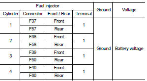
1.CHECK FUEL INJECTOR POWER SUPPLY CIRCUIT
1. Turn ignition switch OFF.
2. Disconnect fuel injector harness connector.
3. Turn ignition switch ON.
4. Check the voltage between fuel injector harness connector and ground.
Is the inspection result normal? YES >> GO TO 3.
NO >> GO TO 2.
2.DETECT MALFUNCTIONING PART
Check the following.
ŌĆó Harness connectors E8, F1
ŌĆó IPDM E/R connector E15
ŌĆó 15 A fuse (No. 62)
ŌĆó Harness for open or short between fuel injector and fuse
>> Repair open circuit or short to ground or short to power in harness or connectors.
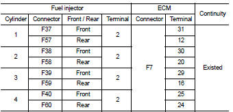
3.CHECK FUEL INJECTOR OUTPUT SIGNAL CIRCUIT FOR OPEN AND SHORT
1. Turn ignition switch OFF.
2. Disconnect ECM harness connector.
3. Check the continuity between fuel injector harness connector and ECM harness connector.
4. Also check harness for short to ground and short to power.
Is the inspection result normal? YES >> GO TO 4.
NO >> Repair open circuit or short to ground or short to power in harness or connectors.
4.CHECK FUEL INJECTOR
Refer to EC-779, "Component Inspection".
Is the inspection result normal? YES >> GO TO 5.
NO >> Replace malfunctioning fuel injector.
5.CHECK INTERMITTENT INCIDENT
Refer to GI-42, "Intermittent Incident".
Is the inspection result normal? YES >> Replace IPDM E/R.
NO >> Repair or replace harness or connectors.
Component Inspection
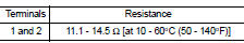
1.CHECK FUEL INJECTOR
1. Turn ignition switch OFF.
2. Disconnect fuel injector harness connector.
3. Check resistance between fuel injector terminals as follows.
Is the inspection result normal? YES >> INSPECTION END
NO >> Replace malfunctioning fuel injector.
 Electrical load signal
Description
The electrical load signal (Headlamp switch signal, rear window defogger
switch signal, etc.) is transferred to
ECM through the CAN communication line.
Component Function Check
1.CHE ...
 Fuel pump
Component Function Check
1.CHECK FUEL PUMP FUNCTION
1. Turn ignition switch ON.
2. Pinch fuel feed hose with two fingers.
Fuel pressure pulsation should be felt on the fuel feed
hose for 1 second ...
Other materials:
AEB with Pedestrian Detection system operation
Vehicle ahead detection indicator
AEB with Pedestrian Detection emergency warning indicator
AEB with Pedestrian Detection system warning light
The Automatic Emergency Braking (AEB) with Pedestrian Detection system in your Nissan Leaf is en ...
Front drive shaft
Exploded View
LEFT SIDE
1. Circular clip
2. Dust shield
3. Housing assembly
4. Boot band
5. Boot
6. Damper band
7. Dynamic damper
8. Circular clip
9. Joint sub-assembly
: Wheel side
: Fill NISSAN Genuine grease or
equivalent.
: Always replace after every
disassembly.
RIGHT ...
Input shaft and gear
Exploded View
1. Input shaft front bearing
2. Input shaft
3. Snap ring
4. Input shaft rear bearing
5. Adapter plate
6. Bushing
7. 5th input gear
8. 5th-reverse baulk ring
9. Synchronizer lever
10. 5th-reverse synchronizer hub
11. 5th-reverse coupling sleeve
12. Retaining pin
1 ...
