Nissan Juke Service and Repair Manual : Fuel level sensor unit, fuel filter and fuel pump assembly
2WD : Exploded View
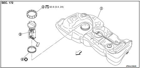
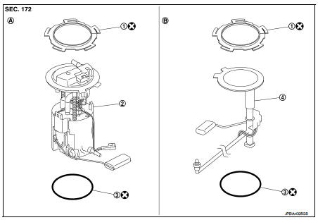
1. Fuel tank
2. Lock ring
3.
Fuel level sensor unit, fuel filter and
fuel pump assembly
4. Rock ring
 Vehicle front
 : N?·m (kg-m, ft-lb)
 : Always replace after every
disassembly.
2WD : Removal and Installation
WARNING:
Read ???General Precautions??? when working on the fuel system. Refer to FL-3,
"General Precautions".
REMOVAL
1. Release the fuel pressure from the fuel lines. Refer to EC-551, "Work Procedure".
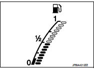
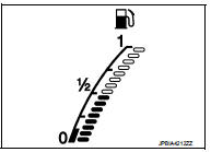
2. Check fuel level on fuel gauge. If fuel gauge indicates more than the level as shown in the figure (full or almost full), drain fuel from fuel tank until fuel gauge indicates level as shown in the figure or below.
NOTE
:
Because fuel will be spilled when removing fuel level sensor
units for the top of the fuel is above the fuel level sensor units
installation surface.
• As a guide, fuel level becomes the position as shown in the figure or below when approximately 25 (6-5/8 US gal, 5-1/4 Imp gal) of fuel are drained from fuel tank.
• In a case that fuel pump does not operate, perform the following procedure.
a. Insert hose of less than 25 mm (0.98 in) in diameter into fuel filler tube through fuel filler opening to draw fuel from fuel filler tube.
b. Disconnect fuel filler hose from fuel filler tube. Refer to FL-18, "2WD : Exploded View".
c. Insert hose into fuel tank through fuel filler hose to draw fuel from fuel tank.
3. Open fuel filler lid.
4. Open filler cap and release the pressure inside fuel tank.
5. Remove rear seat. Refer to SE-32, "Exploded View".
6. Remove inspection hole cover.
• Using a screwdriver, remove it by turning clips clockwise by 90 degrees.
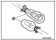
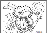
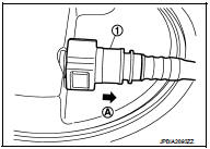
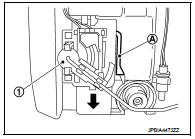
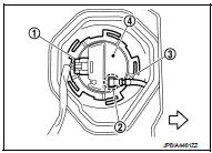
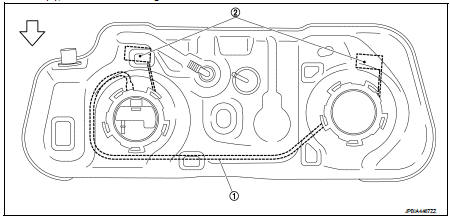
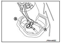
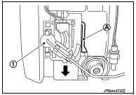
7. Disconnect harness connector (1), fuel feed hose (4) and quick connector (3).
2 : Fuel level sensor unit, fuel filter and fuel pump assembly
 : Vehicle front
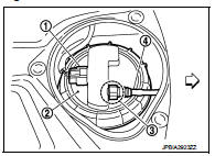
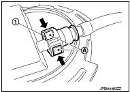
• Remove quick connector in the following procedures.
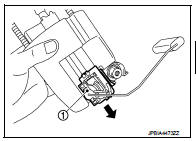
- Pinch quick connector square-part (A) with your fingers, and pull out the quick connector (1) by hand.
- If quick connector and tube on sender unit are stuck, push and pull several times until they move, and pull out.
CAUTION:
• Quick connector can be removed when the tabs are completely
depressed. Never twist it more than necessary.
• Never use any tools to disconnected quick connector.
• Keep resin tube away from heat. Be especially careful when welding near the resin tube.
• Prevent acid liquid such as battery electrolyte, etc. from getting on resin tube.
• Never bend or twist resin tube during installation and disconnection.
• To keep the connecting portion clean and to avoid damage and foreign materials, cover them completely with plastic bags (A) or something similar.
• Never insert plug, preventing damage on O-ring in quick connector.
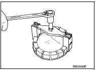
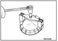
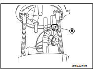
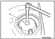
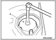
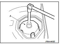
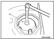
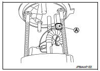
8. Remove lock ring for fuel level sensor unit, fuel filter and fuel pump assembly with fuel tank lock ring wrench [SST: KV99104700] (A) by turning counterclockwise.
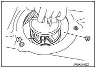
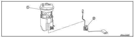
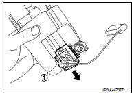
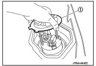
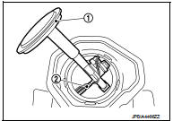
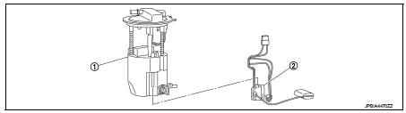
9. Remove fuel level sensor unit, fuel filter and fuel pump assembly (1).
CAUTION:
• Never bend float arm (2) during removal.
• Never pollute the inside by residue fuel. Draw out avoiding inclination by supporting with a cloth.
• Never cause impacts such by dropping when handling components.
INSTALLATION
Note to the following, and install in the reverse order of removal.
Fuel Level Sensor Unit
1. Temporarily install the O-ring to the fuel level sensor unit.
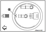
2. Insert the fuel level sensor unit to the fuel tank, and then install the temporarily installed O-ring (Step 1) to the opening of the fuel tank.
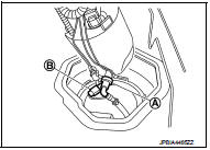
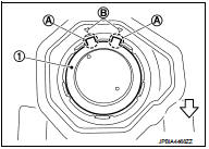
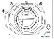
3. Install fuel level sensor unit to fuel tank with alignment mark (B) on the upper surface facing the tree inscribed lines (A) on the tank side.
 : Vehicle front
CAUTION:
• Never allow O-ring to drop.
• Never bend float arm during installing.
4. Install lock ring for fuel level sensor unit, fuel filter and fuel pump assembly with lock ring wrench [SST: KV993G0010 or KV99104700] by turning clockwise.
CAUTION:
Install lock ring horizontally.
Quick Connector
Connect quick connector as follows:
1. Check the connection for damage or any foreign materials.
2. Align the connector with the tube, then insert the connector straight into the tube until a click sound is heard.
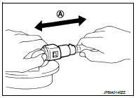
3. After connecting, check that the connection is secure by following method.
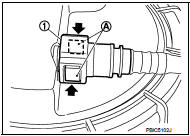
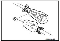
• Visually confirm that the two tabs are connected to the connector.
• Pull (A) the tube and the connector to check they are securely connected.
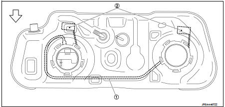
1 : Quick connector
2WD : Disassembly and Assembly
Unit Disassembly and Assembly
Disassembly
1.
Fuel level sensor unit, fuel filter and
fuel pump assembly
2. Fuel gauge
1. Disconnect harness connector(A).
2. Press (A) with a flat-blade screwdriver or an equivalent to release lock and push out the fuel gauge(1).
3. To remove the fuel gauge(1), side it in the direction (A) of the arrow with the lock release.
Assembly
CAUTION:
Sub fuel level sensor unit cannot be disassembled and should be replaced as a
unit.
1. Check for damage of fuel level sensor unit installation position on the side of fuel filter and pump assembly.
2. Slide fuel level sensor unit until it aligns to installation groove, then insert it until stops.
• After inserting, apply force in reverse direction (removal direction) to ensure it cannot be pulled out.
3. Connect harness connector.
2WD : Inspection
INSPECTION AFTER INSTALLATION
Use the following procedure to check for fuel leakage.
1. Turn ignition switch ???ON??? (with engine stopped), then check connections for leakage by applying fuel pressure to fuel piping.
2. Start engine and let it idle and check there are no fuel leakage at the fuel system connections.
4WD : Exploded View
1. Lock ring
2.
Fuel level sensor unit, fuel filter and fuel pump
assembly
3. O-ring
4. Sub fuel level sensor assembly
A. Right side
B. Left side
 : Always replace after every
disassembly.
CAUTION:
Never remove or disassemble parts unless instructed as shown in the figure.
4WD : Removal and Installation
REMOVAL
Fuel Level Sensor Unit, Fuel Filter and Fuel Pump Assembly
WARNING:
Be sure to read ???General Precautions??? before working on the fuel system. Refer
to FL-3, "General Precautions".
1. Release the fuel pressure from the fuel lines. Refer to XX-XX, "*****".
2. Check fuel level on fuel gauge. If fuel gauge indicates more than the level as shown in the figure (full or almost full), drain fuel from fuel tank until fuel gauge indicates level as shown in the figure or below.
NOTE
:
Because fuel will be spilled when removing fuel level sensor
units for the top of the fuel is above the fuel level sensor units
installation surface.
• As a guide, fuel level becomes the position as shown in the figure or below when approximately 25 (6-5/8 US gal, 5-1/4 Imp gal) of fuel are drained from fuel tank.
• In a case that fuel pump does not operate, perform the following procedure.
a. Insert hose of less than 25 mm (0.98 in) in diameter into fuel filler tube through fuel filler opening to draw fuel from fuel filler tube.
b. Disconnect fuel filler hose from fuel filler tube. Refer to XX-XX, "*****".
c. Insert hose into fuel tank through fuel filler hose to draw fuel from fuel tank.
3. Open fuel filler lid.
4. Open filler cap and release the pressure inside fuel tank.
5. Remove rear seat cushion. Refer to SE-41, "Exploded View".
6. Remove inspection hole cover.
7. Disconnect harness connector (1) and quick connector (2).
3 : Fuel feed hose
4 : Fuel level sensor unit, fuel filter and fuel pump.
 : Vehicle front
• Remove quick connector in the following procedures.
- Pinch quick connector square-part (A) with your fingers, and pull out the quick connector (1) by hand.
- If quick connector and tube on sender unit are stuck, push and pull several times until they move, and pull out.
CAUTION:
• Quick connector can be removed when the tabs are completely
depressed. Never twist it more than necessary.
• Never use any tools to disconnected quick connector.
• Keep resin tube away from heat. Be especially careful when welding near the resin tube.
• Prevent acid liquid such as battery electrolyte, etc. from getting on resin tube.
• Never bend or twist resin tube during installation and disconnection.
• To keep the connecting portion clean and to avoid damage and foreign materials, cover them completely with plastic bags (A) or something similar.
• Never insert plug, preventing damage on O-ring in quick connector.
8. Using lock ring wrench (A) (commercial service tool), remove lock ring.
NOTE
:
For reference when installing, put a matching mark on lock ring,
fuel pump assembly and fuel tank.
9. Raise fuel level sensor unit, fuel filter and fuel pump assembly (1).
CAUTION:
• Never bend float arm during removal.
• Never pollute the inside by residue fuel. Draw out avoiding inclination by supporting with a cloth.
• Never cause impacts such by dropping when handling components.
10. Separate fuel tube as per the following steps to remove fuel level sensor unit, fuel filter and fuel pump assembly.
• Pinch quick connector (A) square-part with your fingers, and pull out the quick connector by hand.
• If quick connector and tube on sender unit are stuck, push several times until they move, and pull out.
NOTE
:
When separating the fuel tube, tie a gasoline-resistance rope to the tip of the fuel tube and leave the rope on the fuel tank side to easily pull the fuel tube for installation.
• Disconnect harness connector (B).
Sub Fuel Level Sensor Assembly 1. Remove fuel level sensor unit, fuel filter and fuel pump assembly.
2. Use lock ring wrench (A) (commercial service tool) to remove lock ring.
3. Remove sub fuel level sensor assembly (1).
CAUTION:
• Never disassemble a fuel tube (2) from sub fuel sensor
assembly.
• Never bend float arm during removal.
• Never pollute the inside by residue fuel. Draw out avoiding inclination by supporting with a cloth.
• Never cause impacts such by dropping when handling components.
NOTE:
Tie a gasoline-resistance rope to a tip of the tube. Draw and leave the rope to the fuel tank side so that the rope can be the guide for installation.
INSTALLATION
Note the following, and install in the reverse order of removal.
Sub Fuel Level Sensor Assembly 1. Install O-ring to fuel tank without any twist.
2. Using the rope left on the fuel tank side at removal, run the fuel tube inside the fuel tank to install the sub fuel level sensor assembly to the fuel tank.
CAUTION:
• Never bend float arm during installation.
• To install, fuel tube (1) must run to the front ( ) of the vehicle to avoid the interference with the float arm (2), as shown in the figure.
3. Install sub fuel level sensor assembly (1) with its matching mark (A) aligned with fuel tank matching mark (B) as shown in the figure.
 : Vehicle front
NOTE
:
• Figure shows fuel level sensor unit, fuel filter and fuel pump
assembly side of fuel tank.
• For sub fuel level sensor assembly matching mark is located on the fuel tank of the vehicle front side.
4. Use lock ring wrench (A) (commercial service tool) to remove lock ring as per the following steps.
Fuel Level Sensor Unit, Fuel Filter and Fuel Pump Assembly 1. Temporarily install the O-ring to the fuel level sensor unit, fuel filter and fuel pump assembly.
2. Connect the fuel tube as per the following steps.
• Insert the quick connector (A) straight to the fuel level sensor unit, fuel filter and fuel pump assembly.
• Judge a good fit from connecting sound and tactile feedback.
• Pull the fuel tube by hand to check a secure fit.
3. Connect harness connector (B).
4. Insert the fuel level sensor unit, fuel filter and fuel pump assembly to the fuel tank.
CAUTION:
• Never bend float arm during installation.
• To install, fuel tube (1) must run to the front (
) of the vehicle to avoid the interference with the
float arm (2), as shown in the figure.
5. Install fuel level sensor unit, fuel filter and fuel pump assembly (1) with its matching mark (A) aligned with fuel tank matching mark (B) as shown in the figure.
NOTE
:
 : Vehicle front
6. Use lock ring wrench (A) (commercial service tool) to remove lock ring as per the following steps.
7. Connect quick connector of fuel feed tube as per following procedures.
a. Check the connection for damage or any foreign materials.
b. Align the connector with the tube, then insert the connector straight into the tube until a ???click??? sound is heard.
c. After connecting, check that the connection is secured with following procedures.
• Visually confirm that the two tabs are connected to the connector.
• Pull (A) the tube and the connector to check that they are securely connected.
8. Connect harness connector.
Inspection Hole Cover • Before installing inspection hole cover, check that the connecting part has no fuel leakage. Refer to FL-10, "2WD : Inspection".
1. Install inspection hole covers with the front mark (arrow) facing front of vehicle.
4WD : Disassembly and Assembly
Unit Disassembly and Assembly
Disassembly
1.
Fuel level sensor unit, fuel filter and
fuel pump assembly
2. Fuel gauge
1. Disconnect harness connector(A).
2. Press (A) with a flat-blade screwdriver or an equivalent to release lock and push out the fuel gauge(1).
3. To remove the fuel gauge(1), side it in the direction (A) of the arrow with the lock release.
Assembly
CAUTION:
Sub fuel level sensor unit cannot be disassembled and should be replaced as a
unit.
1. Check for damage of fuel level sensor unit installation position on the side of fuel filter and pump assembly.
2. Slide fuel level sensor unit until it aligns to installation groove, then insert it until stops.
• After inserting, apply force in reverse direction (removal direction) to ensure it cannot be pulled out.
3. Connect harness connector.
4WD : Inspection
INSPECTION AFTER INSTALLATION
Use the following procedure to check for fuel leakage.
1. Turn ignition switch ???ON??? (with engine stopped), then check connections for leakage by applying fuel pressure to fuel piping.
2. Start engine and let it idle and check there are no fuel leakage at the fuel system connections.

 Fuel tank
2WD : Exploded View
1. Fuel filler cap
2. Grommet
3. Fuel filler tube
4. EVAP canister hose
5. Fuel tank mounting band (RH)
6. Fuel tank mounting band (LH)
7. Fuel tank
8. Clamp
9. Fu ...
Other materials:
Aluminum alloy wheels
Wash regularly with a sponge dampened in a mild soap solution, especially during
winter months in areas where road salt is used. Salt could discolor the wheels if
not removed.
CAUTION
Follow the directions below to avoid staining or discoloring the wheels:
• Do not use a cleaner that uses str ...
Component parts
Component Parts Location
1. BCM
Refer to BCS-6, "BODY CONTROL
SYSTEM : Component Parts Location"
(with Intelligent Key) or BCS-96,
"BODY CONTROL SYSTEM : Component
Parts Location" (without Intelligent
Key)
2. Power window main switch
3. Front power window motor (drive ...
Catalyst
2WD
2WD : Exploded View
1. A/F sensor 1
2. Catalyst convertor shroud upper
3. Gasket
4. Catalyst
5. Catalyst convertor support bracket rear
6. Catalyst convertor bracket (RH)
A. To exhaust system
: Engine front
: N·m (kg-m, ft-lb)
: N·m (kg-m, in-lb)
: Always replace after every
...
