Nissan Juke Service and Repair Manual : Catalyst
2WD
2WD : Exploded View
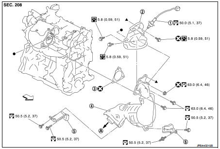
1. A/F sensor 1
2. Catalyst convertor shroud upper
3. Gasket
4. Catalyst
5. Catalyst convertor support bracket rear
6. Catalyst convertor bracket (RH)
A. To exhaust system
 : Engine front
 : N·m (kg-m, ft-lb)
 : N·m (kg-m, in-lb)
 : Always replace after every
disassembly.
2WD : Removal and Installation
REMOVAL
1. Remove engine cover. Refer to EM-25, "Exploded View".
2. Remove cowl top extension. Refer to EXT-20, "Exploded View".
3. Remove front tube. Refer to EX-5, "Exploded View".
4. Remove A/F sensor 1.
• Using heated oxygen sensor wrench [SST: KV10117100], remove A/F sensor 1.
CAUTION:
Handle A/F sensor 1 carefully and avoid impacts.
5. Remove catalyst convertor shroud upper.
6. Remove bolts and nut of catalyst convertor turbocharger side.
7. Remove support bracket (RH).
8. Remove drive shaft insulator. Refer to 9. Remove catalyst convertor.
INSTALLATION
1. Install catalyst convertor with the following procedure.
• Tighten in numerical order as shown in the figure.
- Install catalyst convertor (base on stud position 1).
- Temporary assemble 2 (no priority).
- Temporary assemble 3, 4.
- Tightening 5, 6 and 7.
- Tightening again 8, 9 and 10.
- Temporary assemble 11.
- Tightening 12,13,14,and 15.
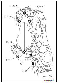
2. Install in the reverse order of removal after this step.
4WD
4WD : Exploded View
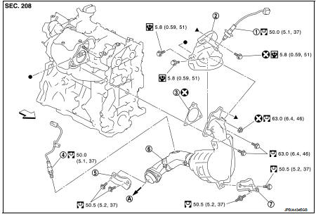
1. A/F sensor 1
2. Catalyst convertor shroud upper
3. Gasket
4. Heated oxygen sensor 2
5. Catalyst convertor upport bracket rear
6. Catalyst convertor
7. Catalyst convertor support bracket (RH)
A. To exhaust system
Engine front
: N·m (kg-m, ft-lb)
: N·m (kg-m, in-lb)
: Always replace after every
disassembly.
4WD : Removal and Installation
REMOVAL
1. Drain engine coolant. Refer to CO-11, "Draining".
2. Remove engine cover. Refer to EM-25, "Exploded View".
3. Remove cowl top extension. Refer to EXT-20, "Exploded View".
4. Remove front tube. Refer to EX-5, "Exploded View" 5. Remove A/F sensor 1.
6. Remove catalyst convertor shroud upper.
7. Remove bolts and nut of catalyst convertor turbocharger side.
8. Remove drive shaft insulator.
9. Remove support bracket (RH).
10. Move catalyst convertor.
11. Remove turbocharger. Refer to EM-36, "Exploded View".
12. Remove catalyst convertor.
INSTALLATION
1. Install catalyst convertor with the following procedure.
• Tighten in numerical order as shown in the figure.
- Install catalyst convertor (base on stud position 1).
- Temporary assemble 2 (no priority).
- Temporary assemble 3, 4.
- Tightening 5, 6 and 7.
- Tightening again 8, 9 and 10.
- Temporary assemble 11.
- Tightening 12,13,14,and 15.
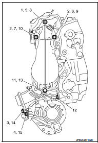
2. Install in the reverse order of removal after this step.
 Charge air cooler
Exploded View
1. Air inlet tube assembly
2. Air inlet tube bracket
3. Clamp
4. Air inlet hose
5. Gasket
6. Turbocharger
7. Mounting rubber
8. Charge air cooler
9. Air inlet tube assem ...
 Turbocharger
Exploded View
1. Heat insulator
2. Actuator hose
3. Clamp
4. Turbocharger inlet tube
5. Gasket
6. Gasket
7. Clamp
8. Oil outlet hose
9. Oil return pipe
10. Oil supply tube
11. O-ri ...
Other materials:
B26F4 starter control relay
DTC Logic
DTC DETECTION LOGIC
NOTE:
• If DTC B26F4 is displayed with DTC U1000, first perform the trouble diagnosis
for DTC U1000. Refer to
BCS-83, "DTC Logic".
• If DTC B26F4 is displayed with DTC U1010, first perform the trouble diagnosis
for DTC U1010. Refer to
BCS-84, &qu ...
Door does not lock/unlock with door key cylinder operation
Diagnosis Procedure
1.CHECK POWER DOOR LOCK OPERATION
Check power door lock operation.
Does door lock/unlock with door lock and unlock switch?
YES >> GO TO 2.
NO >> Go to DLK-110, "ALL DOOR : Diagnosis Procedure".
2.CHECK UNLOCK SENSOR
Check unlock sensor.
Refer ...
P0850 PNP switch
Description
When the selector lever position is P or N (CVT), Neutral position (M/T),
park/neutral position (PNP) signal is
ON.
DTC Logic
DTC DETECTION LOGIC
DTC CONFIRMATION PROCEDURE
1.INSPECTION START
Do you have CONSULT-III?
Do you have CONSULT-III?
YES >> GO TO 2.
NO >& ...
