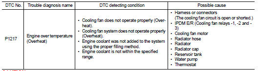
Nissan Juke Service and Repair Manual : P1217 engine over temperature
DTC Logic
DTC DETECTION LOGIC
NOTE
:
• If DTC P1217 is displayed with DTC U1001, first perform the trouble diagnosis
for DTC U1001. Refer
to EC-569, "DTC Logic".
• If DTC P1217 is displayed with DTC P0607, first perform the trouble diagnosis for DTC P0607. Refer to EC-685, "DTC Logic".
If the cooling fan or another component in the cooling system malfunctions, engine coolant temperature will rise.
When the engine coolant temperature reaches an abnormally high temperature condition, a malfunction is indicated.
CAUTION:
When a malfunction is indicated, be sure to replace the coolant. Refer to CO-38,
"Refilling". Also,
replace the engine oil. Refer to LU-26, "Refilling".
1. Fill radiator with coolant up to specified level with a filling speed of 2 liters per minute. Be sure to use coolant with the proper mixture ratio. Refer to MA-14, "Engine Coolant Mixture Ratio".
2. After refilling coolant, run engine to ensure that no water-flow noise is emitted.
DTC CONFIRMATION PROCEDURE
1.PERFORM COMPONENT FUNCTION CHECK
Perform component function check. Refer to EC-692, "Component Function Check".
NOTE
:
Use component function check to check the overall function of the cooling fan.
During this check, a DTC might
not be confirmed.
Is the inspection result normal? YES >> INSPECTION END
NO >> Go to EC-693, "Diagnosis Procedure".
Component Function Check
1.PERFORM COMPONENT FUNCTION CHECK-I
WARNING:
Never remove the radiator cap when the engine is hot. Serious burns could be
caused by high pressure
fluid escaping from the radiator.
Wrap a thick cloth around cap. Carefully remove the cap by turning it a quarter turn to allow built-up pressure to escape. Then turn the cap all the way off.
Check the coolant level in the reservoir tank and radiator.
Allow engine to cool before checking coolant level.
Is the coolant level in the reservoir tank and/or radiator below the proper range? YES >> Go to EC-693, "Diagnosis Procedure".
NO >> GO TO 2
2.PERFORM COMPONENT FUNCTION CHECK-II
Confirm whether customer filled the coolant or not.
Did customer fill the coolant? YES >> Go to EC-693, "Diagnosis Procedure".
NO >> GO TO 3.
3.PERFORM COMPONENT FUNCTION CHECK-III
 With CONSULT-III
1. Turn ignition switch ON.
2. Perform “COOLING FAN” in “ACTIVE TEST” mode with CONSULT-III and touch “LOW” on the CONSULT- III screen.
3. Make sure that cooling fan operates at low speed.
 Without CONSULT-III
1. Start engine and let it idle.
2. Turn air conditioner switch and blower fan switch ON.
3. Make sure that cooling fan operates at low speed.
Is the inspection result normal? YES >> GO TO 4.
NO >> Go to EC-693, "Diagnosis Procedure".
4.PERFORM COMPONENT FUNCTION CHECK-IV
With CONSULT-III
1. Touch “HI” on the CONSULT-III screen.
2. Make sure that cooling fan operates at higher speed than low speed.
Without CONSULT-III
1. Turn ignition switch OFF.
2. Turn air conditioner switch and blower fan switch OFF.
3. Disconnect engine coolant temperature sensor harness connector.
4. Connect 150Ω resistor to engine coolant temperature sensor harness connector.
5. Restart engine and make sure that cooling fan operates at higher speed than low speed.
Is the inspection result normal? YES >> INSPECTION END
NO >> Go to EC-693, "Diagnosis Procedure".
Diagnosis Procedure
1.CHECK COOLING FAN OPERATION
 With CONSULT-III
1. Turn ignition switch ON.
2. Perform “COOLING FAN” in “ACTIVE TEST” mode with CONSULT-III.
3. Make sure that cooling fan motor operate at each speed (LOW/HI).
 Without CONSULT-III
1. Perform IPDM E/R auto active test and check cooling fan motor operation. Refer to PCS-12, "Diagnosis Description" (WITH I-KEY) or PCS-43, "Diagnosis Description" (WITHOUT I-KEY).
2. Make sure that cooling fan motor operate at each speed (Low/High).
Is the inspection result normal? YES >> GO TO 2.
NO >> Go to EC-774, "Diagnosis Procedure".
2.CHECK COOLING SYSTEM FOR LEAK-I
Check cooling system for leak. Refer to CO-11, "Inspection".
Is leakage detected? YES >> GO TO 3.
NO >> GO TO 4.
3.CHECK COOLING SYSTEM FOR LEAK-II
Check the following for leak.
• Hose (Refer to CO-27, "Inspection".) • Radiator (Refer to CO-19, "Inspection".) • Water pump (Refer to CO-22, "Inspection".)
>> Repair or replace malfunctioning part.
4.CHECK RADIATOR CAP
Check radiator cap. Refer to CO-15, "RADIATOR CAP : Inspection".
Is the inspection result normal? YES >> GO TO 5.
NO >> Replace radiator cap.
5.CHECK THERMOSTAT
Check thermostat. Refer to CO-25, "Inspection".
Is the inspection result normal? YES >> GO TO 6.
NO >> Replace thermostat.
6.CHECK ENGINE COOLANT TEMPERATURE SENSOR
Refer to EC-596, "Component Inspection".
Is the inspection result normal? YES >> GO TO 7.
NO >> Replace engine coolant temperature sensor.
7.OVERHEATING CAUSE ANALYSIS
If the cause cannot be isolated, check CO-35, "Troubleshooting Chart".
>> INSPECTION END
 P1212 TCS communication line
Description
This CAN communication line is used to control the smooth engine operation
during the TCS operation. Pulse
signals are exchanged between ECM and “ABS actuator and electric unit (cont ...
 P1220 fuel pump control module (FPCM)
DTC Logic
DTC DETECTION LOGIC
DTC CONFIRMATION PROCEDURE
1.PRECONDITIONING
1. Turn ignition switch OFF and wait at least 10 seconds.
2. Turn ignition switch ON.
3. Turn ignition switch OFF and ...
Other materials:
Front fender
Exploded View
1. Front fender assembly
2. Front fender stiffener
: Vehicle fr
Removal and Installation
REMOVAL
1. Remove front fillet molding. Refer to EXT-26, "FRONT FILLET MOLDING :
Removal and Installation".
2. Remove front bumper fascia assembly. Refer to EXT-13, "Remo ...
LAN System can system (type 4)
DTC/CIRCUIT DIAGNOSIS
Main line between IPDM-E and DLC circuit
Diagnosis Procedure
1.CHECK CONNECTOR
1. Turn the ignition switch OFF.
2. Disconnect the battery cable from the negative terminal.
3. Check the following terminals and connectors for damage, bend and loose
connection (connector s ...
P range interlock door lock/unlock function does not operate
Diagnosis Procedure
1.CHECK “AUTOMATIC LOCK/UNLOCK SELECT” SETTING IN “WORK SUPPORT”
1. Select “DOOR LOCK” of “BCM” using CONSULT-III.
2. Select “AUTOMATIC LOCK/UNLOCK SELECT” in “WORK SUPPORT” mode.
3. Check “AUTOMATIC LOCK/UNLOCK SELECT” setting in “WORK SUPPORT†...
