Nissan Juke Service and Repair Manual : Front fender
Exploded View
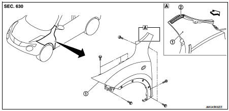
1. Front fender assembly 2. Front fender stiffener
 : Vehicle fr
Removal and Installation
REMOVAL
1. Remove front fillet molding. Refer to EXT-26, "FRONT FILLET MOLDING : Removal and Installation".
2. Remove front bumper fascia assembly. Refer to EXT-13, "Removal and Installation".
3. Remove sill cover. Refer to EXT-23, "Removal and Installation".
4. Remove fender protector. Refer to EXT-22, "Removal and Installation".
5. Remove front fender cover. Refer to EXT-20, "Exploded View".
6. Remove front combination lamp. Refer to EXL-91, "Removal and Installation".
7. Remove side turn signal lamp. Refer to EXL-98, "Removal and Installation".
8. Remove mounting bolts of front fender assembly.
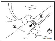
9. Remove front fender stiffener (2) from the vehicle body while carefully pulling upper portion of front fender (1) toward vehicle outside.
 : Vehicle front
10. Remove front fender assembly.
CAUTION
:
An viscous urethane foam is installed on the back surface of front fender.
When removing the
front fender, be careful to not deform the front fender while performing the
procedure and removing
the viscous urethane foam a little at a time.
INSTALLATION
Note the following items, and install in the reverse order of removal.
CAUTION:
ŌĆó After installation, apply the touch-up paint (the body color) onto the head of
front fender mounting
bolts.
ŌĆó After installation, adjust the following part.
- Hood assembly: Refer to DLK-305, "HOOD ASSEMBLY : Adjustment".
- Front door: Refer to DLK-319, "DOOR ASSEMBLY : Adjustment".
 Radiator core support
HR16DE
HR16DE : Exploded View
1. Radiator core support upper
2. Air guide RH (MT models)
3. Radiator core support lower
4. Air guide LH 5. Air guide (upper)
6. Air guide LH (CVT models)
7. ...
 Front door
Exploded View
1. Front door panel
2. Grommet
3. TORX bolt
4. Door striker
5. Door pad
6. Bumper rubber
7. Door check link
8. Door hinge (lower)
9. Door hinge (upper)
10. Grommet
: D ...
Other materials:
Engine smokes when started
Description
CHART 18: ENGINE SMOKES WHEN STARTED
Diagnosis Procedure
1.CHECK ENGINE OIL
Check the grade of engine oil. Refer to LU-33, "Inspection".
Is the inspection result normal?
YES >> GO TO 2.
NO >> Replace engine oil. Refer to LU-34, "Refilling".
2 ...
Service Equipment
RECOVERY/RECYCLING RECHARGING EQUIPMENT
Be certain to follow the manufacturerŌĆÖs instructions for machine operation
and machine maintenance. Never
introduce any refrigerant other than that specified into the machine.
ELECTRICAL LEAK DETECTOR
Be certain to follow the manufacturerŌĆÖs instruc ...
Door mirror defogger does not operate
Both sides
BOTH SIDES : Description
Both door mirror defoggers do not operate
BOTH SIDES : Diagnosis Procedure
1.CHECK REAR WINDOW DEFOGGER
Check rear window defogger.
Refer to DEF-31, "Component Function Check".
Is the inspection result normal?
YES >> GO TO 2.
NO > ...
