Nissan Juke Service and Repair Manual : Radiator core support
HR16DE
HR16DE : Exploded View
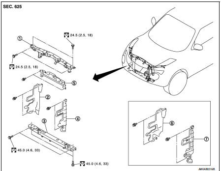
1. Radiator core support upper 2. Air guide RH (MT models) 3. Radiator core support lower 4. Air guide LH 5. Air guide (upper) 6. Air guide LH (CVT models) 7. Air guide RH (CVT models)
 : N·m (kg-m, ft-lb)
HR16DE : Removal and Installation
RADIATOR CORE SUPPORT UPPER
Removal
1. Remove front bumper fascia. Refer to EXT-13, "Removal and Installation".
2. Remove front combination lamp (LH and RH). Refer to EXL-91, "Removal and Installation".
3. Remove headlamp (LH and RH). Refer to EXL-89, "Removal and Installation".
4. Disconnect crash zone sensor harness connector. Refer to SR-26, "Removal and Installation".
CAUTION:
Turn ignition switch OFF, disconnect battery negative terminal and then wait for
at least 3 minutes.
5. Remove hood lock and hood lock cable fixing clip. Refer to DLK-335, "HOOD LOCK : Removal and Installation".
6. Remove horn bracket. Refer to HRN-4, "Removal and Installation".
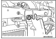
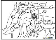
7. Remove air guide (upper) fixing clips, and then remove air guide (upper).
8. Remove upper fixing clips (2) of air guide (LH and RH) (1).
9. Remove hood support rod. Refer to DLK-309, "HOOD SUPPORT ROD : Removal and Installation".
10. Remove mounting bolts, and then remove radiator core support upper.
Installation Install in the reverse order of removal.
RADIATOR CORE SUPPORT LOWER
Removal
1. Remove front bumper fascia. Refer to EXT-13, "Removal and Installation".
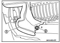
2. Remove lower fixing clips (2) of radiator side seal (LH and RH) (1).
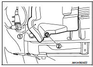
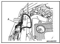
3. Use belts (A) to suspend radiator and condenser to prevent them from falling.
CAUTION:
Never damage radiator and condenser
.
4. Remove mounting bolts, and then remove radiator core support lower.
Installation
Install in the reverse order of removal.
MR16DDT
MR16DDT : Exploded View
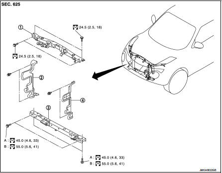
1. Radiator core support upper
2. Air guide RH
3. Radiator core support lower
4. Air guide LH
A : 2WD models
B : 4WD models
 : N·m (kg-m, ft-lb)
MR16DDT : Removal and Installation
RADIATOR CORE SUPPORT UPPER
Removal
1. Remove front bumper fascia. Refer to EXT-13, "Removal and Installation".
2. Remove front combination lamp (LH and RH). Refer to EXL-91, "Removal and Installation".
3. Remove headlamp (LH and RH). Refer to EXL-89, "Removal and Installation".
4. Disconnect crash zone sensor harness connector. Refer to SR-26, "Removal and Installation".
CAUTION:
Turn ignition switch OFF, disconnect battery negative terminal and then wait for
at least 3 minutes.
5. Remove hood lock and hood lock cable fixing clip. Refer to DLK-335, "HOOD LOCK : Removal and Installation".
6. Remove horn bracket. Refer to HRN-4, "Removal and Installation".
7. Remove upper fixing clips (2) of air guide (LH and RH) (1).
8. Remove hood support rod. Refer to DLK-309, "HOOD SUPPORT ROD : Removal and Installation".
9. Remove mounting bolts, and then remove radiator core support upper.
Installation Install in the reverse order of removal.
RADIATOR CORE SUPPORT LOWER
Removal
1. Remove front bumper fascia. Refer to EXT-13, "Removal and Installation".
2. Remove lower fixing clips (2) of radiator side seal (LH and RH) (1).
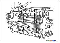
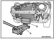
3. Using strings (A), hang inlet hose (1) and inlet hose (2) together with charge air cooler.
CAUTION
:
Never damage inlet hoses with charge air cooler.
4. Support lower side radiator using wooden blocks (B) and a floor jack (A).
CAUTION:
Never damage radiator.
5. Remove mounting bolts, and then remove radiator core support lower.
Installation
Install in the reverse order of removal.
 Hood
Hood
Exploded View
1. Hood assembly
2. Hood bumper rubber
3. Radiator core seal
4. Hood bumper rubber
5. Clamp
6. Hood hinge
7. Grommet
8. Hood support rod
: Clip
: Pawl
: Body grease
Ho ...
 Front fender
Exploded View
1. Front fender assembly
2. Front fender stiffener
: Vehicle fr
Removal and Installation
REMOVAL
1. Remove front fillet molding. Refer to EXT-26, "FRONT FILLET MOLDING :
...
Other materials:
Waxing
Regular waxing protects the paint surface and helps retain new vehicle appearance.
Polishing is recommended to remove built-up wax residue and to avoid a weathered
appearance before reapplying wax.
A NISSAN dealer can assist you in choosing the proper product.
• Wax your vehicle only after a ...
B257B, B257C ambient sensor
DTC Logic
DTC DETECTION LOGIC
NOTE:
• If DTC is displayed along with DTC U1000, first perform the trouble diagnosis
for DTC U1000. Refer to HAC-
275, "DTC Logic".
• If DTC is displayed along with DTC U1010, first perform the trouble diagnosis
for DTC U1010. HAC-276,
"DTC ...
Continuously Variable Transmission (CVT)
The Continuously Variable Transmission (CVT) in your vehicle is electronically
controlled to produce maximum power and smooth operation.
The recommended operating procedures for this transmission are shown on the following
pages.
Follow these procedures for maximum vehicle performance and driv ...
