Nissan Juke Service and Repair Manual : DTC/circuit diagnosis
Blower motor
Diagnosis Procedure
1.CHECK SYMPTOM
Check symptom (A or B).
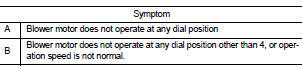
Which symptom is detected? A >> GO TO 2.
B >> GO TO 7.
2.CHECK FUSE
1. Turn ignition switch OFF.
2. Check 15A fuses (Nos. 14 and 16, located in fuse block (J/B)].
NOTE
:
Refer to PG-22, "Fuse, Connector and Terminal Arrangement".
Is the inspection result normal? YES >> GO TO 3.
NO >> Replace the blown fuse after repairing the affected circuit if a fuse is blown.
3.CHECK BLOWER MOTOR POWER SUPPLY
1. Disconnect blower motor connector.
2. Turn ignition switch ON.
3. Check voltage between blower motor harness connector and ground.
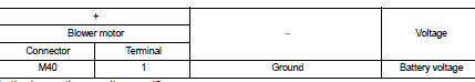
Is the inspection result normal? YES >> GO TO 5.
NO >> GO TO 4.
4.CHECK BLOWER RELAY
1. Turn ignition switch OFF.
2. Check blower relay. Refer to HAC-327, "Component Inspection (Blower Relay)".
Is the inspection result normal? YES >> Repair harness or connector between blower motor and fuse.
NO >> Replace blower relay.
5.CHECK FAN SWITCH GROUND CIRCUIT FOR OPEN
1. Turn ignition switch OFF.
2. Disconnect heater control connector.
3. Check continuity between heater control harness connector and ground.
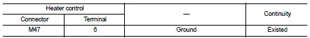
Is the inspection result normal? YES >> GO TO 6.
NO >> Repair harness or connector.
6.CHECK FAN SWITCH 4 POSITION CIRCUIT FOR OPEN
Check continuity between heater control harness connector and blower motor harness connector.
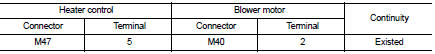
Is the inspection result normal? YES >> GO TO 10.
NO >> Repair the harness or connector.
7.CHECK BLOWER FAN RESISTOR POWER SUPPLY
1. Turn ignition switch OFF.
2. Disconnect blower fan resistor connector.
3. Turn ignition switch ON.
4. Check voltage between blower fan resistor harness connector and ground.
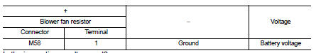
Is the inspection result normal? YES >> GO TO 8.
NO >> Repair harness or connector between blower fan resistor and blower motor.
8.CHECK BLOWER FAN RESISTOR
1. Turn the ignition switch OFF.
2. Check blower fan resistor. Refer to HAC-327, "Component Inspection (Blower Fan Resistor)".
Is the inspection result normal? YES >> GO TO 9.
NO >> Replace blower fan resistor. Refer to HAC-332, "Removal and Installation".
9.CHECK FAN SWITCH 1, 2, 3 POSITION CIRCUIT FOR OPEN
Check continuity between heater control harness connector and blower fan resistor.
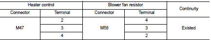
Is the inspection result normal? YES >> GO TO 10.
NO >> Repair harness or connector.
10.CHECK FAN SWITCH
Check fan switch. Refer to HAC-328, "Component Inspection (Fan Switch)".
Is the inspection result normal? YES >> Replace blower motor. Refer to VTL-15, "Removal and Installation (LHD models)" or VTL-16, "Removal and Installation (RHD models)".
NO >> Replace heater control. Refer to HAC-331, "Removal and Installation".
Component Inspection (Blower Motor
)
1.CHECK BLOWER MOTOR
1. Remove blower motor. Refer to VTL-15, "Removal and Installation (LHD models)" or VTL-16, "Removal and Installation (RHD models)".
2. Check that there is not any mixing foreign object in the blower motor.
Is the inspection result normal? YES >> GO TO 2.
NO >> Replace blower motor. Refer to VTL-15, "Removal and Installation (LHD models)" or VTL-16, "Removal and Installation (RHD models)".
2.CHECK BLOWER MOTOR
Check that there is not breakage or damage in the blower motor.
Is the inspection result normal? YES >> GO TO 3.
NO >> Replace blower motor. Refer to VTL-15, "Removal and Installation (LHD models)" or VTL-16, "Removal and Installation (RHD models)".
3.CHECK BLOWER MOTOR
Check that blower motor turns smoothly.
Is the inspection result normal? YES >> INSPECTION END
NO >> Replace blower motor. Refer to VTL-15, "Removal and Installation (LHD models)" or VTL-16, "Removal and Installation (RHD models)".
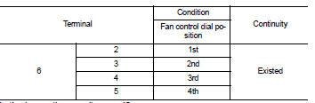
Component Inspection (Blower Relay)
1.CHECK BLOWER RELAY
1. Remove blower relay. Refer to PG-22, "Fuse, Connector and Terminal Arrangement".
2. Check continuity between blower relay terminal 3 and 5 when the voltage is supplied between terminal 1 and 2.
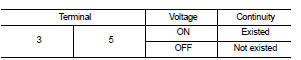
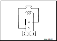
Is the inspection result normal? YES >> INSPECTION END
NO >> Replace blower relay.
Component Inspection (Blower Fan Resistor)
1.CHECK BLOWER FAN RESISTOR
1. Disconnect blower fan resistor connector.
2. Check resistance between blower fan resistor terminals. Refer to applicable table for the normal value.
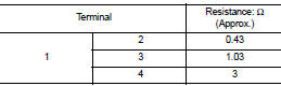
Is the inspection result normal? YES >> INSPECTION END
NO >> Replace blower fan resistor. Refer to HAC-332, "Removal and Installation".
Component Inspection (Fan Switch)
1.CHECK FAN SWITCH
Check continuity between heater control terminals.
Is the inspection result normal? YES >> INSPECTION END
NO >> Replace heater control. Refer to HAC-331, "Removal and Installation".
 Operation inspection
Work Procedure
The purpose of the operational check is to check that the individual system
operates normally.
Check condition : Engine running at normal operating temperature.
1.CHECK BLOWER MOTO ...

Other materials:
Accelerator pedal released position
learning
Description
Accelerator Pedal Released Position Learning is a function of ECM to learn
the fully released position of the
accelerator pedal by monitoring the accelerator pedal position sensor output
signal. It must be performed each
time harness connector of accelerator pedal position sensor ...
System
System Description
Fan speed of blower motor is changed by the combination of fan control dial
(fan switch) operation and blower
fan resistor control.
Door Control
SWITCHES AND THEIR CONTROL FUNCTIONS
1. Intake door
2. Blower motor
3. Air conditioner filter
4. Max. cool door
5. Upper ...
Accelerator pedal released position learning
Description
Accelerator Pedal Released Position Learning is a function of ECM to learn
the fully released position of the
accelerator pedal by monitoring the accelerator pedal position sensor output
signal. It must be performed each
time harness connector of accelerator pedal position sensor ...
