Nissan Juke Service and Repair Manual : CVT position
Inspection and Adjustment
INSPECTION
1. Turn ON the ignition switch with the selector lever at the P position.
2. Press the selector button with the brake pedal depressed, and confirm that the lever can be shifted to positions other than P. Also confirm that shifting is not allowed from the P position to other position without depressing the brake pedal.
3. Move the selector lever and check for “excessive effort”, “sticking”, “noise” or “rattle”.
4. Confirm that selector lever stops at each position with the feel of engagement when it is moved through all the positions. Check whether or not the actual position the selector lever is in matches the position shown by the transaxle body.
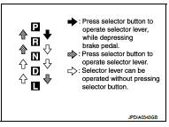
5. Make sure that the selector lever is shifted to all the shift positions in the manner shown in the figure.
6. When the selector button is pressed without applying forward/ backward force to the selector lever at “P”, “R”, “N” and “D” positions, there should be no “sticking” on the button operation.
7. The reverse lamp lights and the reverse warning buzzer sounds at the “R” position and the reverse lamp does not light and the reverse warning buzzer does not sound at other positions. Confirm that the buzzer does not sound when selector lever is in the “P” or “N” position, in particular, with the lever pushed against the “R” position.
8. Check that the engine can be started with the selector lever in the “P” and “N” positions only.
9. Check that the transaxle is locked when the selector lever is in the P position.
ADJUSTMENT
1. Shift the selector lever to the “P” position.
CAUTION:
Rotate the wheels at least a quarter turn and be certain the Park position
mechanism is fully
engaged.
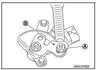
2. Remove nut (A) and set manual lever (B) to the “P” position.
CAUTION:
Do not apply force to the manual lever.
3. Tighten nuts to the specified torque. Refer to TM-485, "Exploded View".
CAUTION:
In tightening, fix the manual lever.
 Line pressure test
Work Procedure
INSPECTION
1. Check the engine oil level. Replenish if necessary. LU-25, "Inspection".
2. Check for leak of the CVT fluid. Refer to TM-480, "Inspection".
3. Driv ...

Other materials:
Clutch pedal
Inspection and Adjustment
INSPECTION
The Height of Clutch Pedal
1. Turn the floor carpet.
2. Check that the clutch pedal height “H1” from the dash lower
panel (1) is within the reference value.
Clutch pedal height
“H1”
: Refer to CL-35, "Clutch Pedal".
3. Replace clutch pe ...
Meters and gauges
1. Tachometer
2. Engine coolant temperature gauge
3. Vehicle information display
— Odometer/twin trip odometer
— Trip computer
— Torque vectoring AWD (AWD model)
— Outside air temperature
4. Fuel gauge
5. Speedometer
6. Warning/indicator lights
7. Instrument brightness ...
AWD warning light
The AWD warning light located in the instrument panel illuminates when the ignition
switch is turned to the ON position. It turns off soon after the engine is started.
If any malfunction occurs in the AWD system while the engine is running, or while
driving, the warning light will either rema ...
