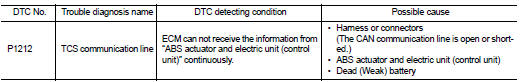
Nissan Juke Service and Repair Manual : P1212 TCS communication line
Description
This CAN communication line is used to control the smooth engine operation during the TCS operation. Pulse signals are exchanged between ECM and “ABS actuator and electric unit (control unit)”.
Be sure to erase the malfunction information such as DTC not only for “ABS actuator and electric unit (control unit)” but also for ECM after TCS related repair.
DTC Logic
DTC DETECTION LOGIC
NOTE
:
• If DTC P1212 is displayed with DTC U1001, first perform the trouble diagnosis
for DTC U1001. Refer
to EC-569, "DTC Logic".
• If DTC P1212 is displayed with DTC P0607, first perform the trouble diagnosis for DTC P0607. Refer to EC-685, "DTC Logic".
Freeze frame data is not stored in the ECM for this self-diagnosis.
DTC CONFIRMATION PROCEDURE
1.PRECONDITIONING
TESTING CONDITION: Before performing the following procedure, confirm that battery voltage is more than 10.5 V at idle.
>> GO TO 2.
2.PERFORM DTC CONFIRMATION PROCEDURE
1. Start engine and let it idle for at least 10 seconds.
2. Check 1st trip DTC.
Is 1st trip DTC detected? YES >> Go to EC-691, "Diagnosis Procedure".
NO >> INSPECTION END
Diagnosis Procedure
Perform trouble diagnosis of ABS actuator and electric unit (control unit). Refer to BRC-145, "Work Flow".
 P0850 PNP switch
Description
When the selector lever position is P or N (CVT), Neutral position (M/T),
park/neutral position (PNP) signal is
ON.
DTC Logic
DTC DETECTION LOGIC
DTC CONFIRMATION PROCEDURE
1.INS ...
 P1217 engine over temperature
DTC Logic
DTC DETECTION LOGIC
NOTE:
• If DTC P1217 is displayed with DTC U1001, first perform the trouble diagnosis
for DTC U1001. Refer
to EC-569, "DTC Logic".
• If DTC P1217 is ...
Other materials:
Forward-facing child restraint installation using the seat belts
WARNING
The three-point seat belt with Automatic Locking Retractor (ALR) must be used
when installing a child restraint.
Failure to use the ALR mode will result in the child restraint not being properly
secured. The restraint could tip over or be loose and cause injury to a child in
a sudden ...
B2193 chain of ECM-IMMU
DTC Logic
DTC DETECTION LOGIC
NOTE:
• If DTC B2193 is displayed with DTC U1000, first perform the trouble diagnosis
for DTC U1000. Refer to
BCS-153, "DTC Logic".
• If DTC B2193 is displayed with DTC U1010, first perform the trouble diagnosis
for DTC U1010. Refer to
BCS-154, & ...
Compression pressure
Inspection
1. Warm up engine thoroughly. Then, stop it.
2. Release fuel pressure. Refer to EC-551, "Work Procedure".
3. Remove ignition coil and spark plug from each cylinder. Refer to EM-178,
"Exploded View".
4. Connect engine tachometer (not required in use of CONSULT-III ...
