Nissan Juke Service and Repair Manual : P0850 PNP switch
Description
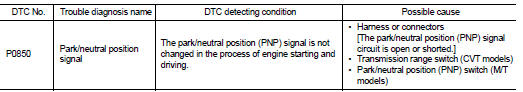
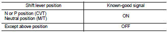
When the selector lever position is P or N (CVT), Neutral position (M/T), park/neutral position (PNP) signal is ON.
DTC Logic
DTC DETECTION LOGIC
DTC CONFIRMATION PROCEDURE
1.INSPECTION START
Do you have CONSULT-III? Do you have CONSULT-III? YES >> GO TO 2.
NO >> GO TO 5.
2.PRECONDITIONING
If DTC Confirmation Procedure has been previously conducted, always turn ignition switch OFF and wait at least 10 seconds before conducting the next test.
>> GO TO 3.
3.CHECK PNP SIGNAL FUNCTION
 With CONSULT-III
1. Turn ignition switch ON.
2. Select “P/N POSI SW” in “DATA MONITOR” mode with CONSULT-III. Then check “P/N POSI SW” signal under the following conditions.
Is the inspection result normal? YES >> GO TO 4.
NO >> Go to EC-689, "Diagnosis Procedure".
4.PERFORM DTC CONFIRMATION PROCEDURE
1. Select “DATA MONITOR” mode with CONSULT-III.
2. Start engine and warm it up to normal operating temperature.
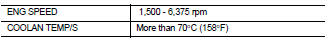
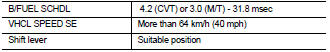
3. Maintain the following conditions for at least 50 consecutive seconds.
CAUTION:
Always drive vehicle at a safe speed.
4. Check 1st trip DTC.
Is 1st trip DTC detected? YES >> Go to EC-689, "Diagnosis Procedure".
NO >> INSPECTION END
5.PERFORM COMPONENT FUNCTION CHECK
Perform component function check. Refer to EC-689, "Component Function Check".
NOTE
:
Use component function check the overall function of the park/neutral position
(PNP) signal circuit. During this
check, a 1st trip DTC might not be confirmed.
Is the inspection result normal? YES >> INSPECTION END
NO >> Go to EC-689, "Diagnosis Procedure".
Component Function Check
1.PERFORM COMPONENT FUNCTION CHECK
1. Turn ignition switch ON.
2. Check the voltage between ECM harness connector and ground.
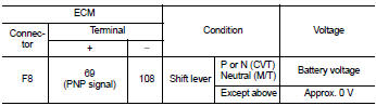
Is the inspection result normal? YES >> INSPECTION END
NO >> Go to EC-689, "Diagnosis Procedure".
Diagnosis Procedure
1.CHECK TRANSMISSION RANGE SWITCH (CVT) OR PARK/NEUTRAL POSITION (PNP) SWITCH (M/T) POWER SUPPLY CIRCUIT
1. Turn ignition switch OFF.
2. Disconnect transmission range switch (CVT) or PNP switch (M/T) harness connector.
3. Turn ignition switch ON.
4. Check the voltage between transmission range switch (CVT) or PNP switch (M/T) harness connector and ground.
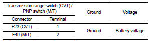
Is the inspection result normal? YES >> GO TO 3.
NO >> GO TO 2.
2.DETECT MALFUNCTIONING PART
Check the following.
• Harness connectors E8, F1 • Harness connectors E105, M77 (M/T) • IPDM E/R harness connector E15 (CVT) • 10 A fuse (No. 5) (M/T) • 10 A fuse (No. 56) (CVT)
• Harness for open or short between transmission range switch (CVT) or PNP switch (M/T) and fuse Is the inspection result normal? >> Repair open circuit or short to ground or short to power in harness or connectors.
3.CHECK PNP SWITCH INPUT SIGNAL CIRCUIT FOR OPEN AND SHORT
1. Turn ignition switch OFF.
2. Disconnect ECM harness connector.
3. Check the continuity between transmission range switch (CVT) or PNP switch (M/T) harness connector and ECM harness connector.
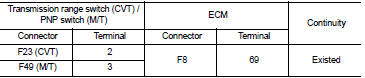
4. Also check harness for short to ground and short to power.
Is the inspection result normal? YES >> GO TO 4.
NO >> Repair open circuit or short to ground or short to power in harness or connectors.
4.CHECK TRANSMISSION RANGE SWITCH (CVT) OR PNP SWITCH (M/T)
Refer to TM-201, "Component Inspection" (CVT) or TM-20, "PARK/NEUTRAL POSITION (PNP) SWITCH : Component Inspection" (M/T).
Is the inspection result normal? YES >> GO TO 5.
NO >> Replace transmission range switch (CVT) or PNP switch (M/T).
5.CHECK INTERMITTENT INCIDENT
Refer to GI-42, "Intermittent Incident".
>> INSPECTION END
 P0643 sensor power supply
DTC Logic
DTC DETECTION LOGIC
DTC CONFIRMATION PROCEDURE
1.PRECONDITIONING
If DTC Confirmation Procedure has been previously conducted, always turn
ignition switch OFF and wait at
least 10 se ...
 P1212 TCS communication line
Description
This CAN communication line is used to control the smooth engine operation
during the TCS operation. Pulse
signals are exchanged between ECM and “ABS actuator and electric unit (cont ...
Other materials:
B2195 anti-scanning
DTC Logic
DTC DETECTION LOGIC
DTC CONFIRMATION PROCEDURE
1.PERFORM DTC CONFIRMATION PROCEDURE
1. Turn ignition switch ON.
2. Check DTC in “Self Diagnostic Result” mode of “BCM” using CONSULT-III.
Is DTC detected?
YES >> Refer to SEC-62, "Diagnosis Procedure".
NO ...
Remote keyless entry receiver
Component Function Check
1.CHECK FUNCTION
1. Select “INTELLIGENT KEY” of “BCM” using CONSULT-III.
2. Select “RKE OPE COUN1” in “DATA MONITOR” mode.
3. Check that the function operates normally according to the following
conditions.
Is the inspection result normal?
YES >& ...
I-LI system operation
Lane Departure Warning (LDW) indicator icon.
Intelligent Lane Intervention (I-LI) status indicator.
ProPILOT Assist control switch (for Nissan Leaf models equipped with advanced driver assistance).
Dynamic driver assistance master switch (fo ...
