Nissan Juke Service and Repair Manual : Headlamp aiming adjustment
LHD
LHD : Description
PREPARATION BEFORE ADJUSTING
NOTE
:
ŌĆó For details, refer to the regulations in your own country.
ŌĆó Perform aiming if the vehicle front body has been repaired and/or the headlamp assembly has been replaced.
Before performing aiming adjustment, check the following.
ŌĆó Adjust the tire pressure to the specification.
ŌĆó Fill with fuel, engine coolant and each oil.
ŌĆó Maintain the unloaded vehicle condition. (Remove luggage from the passenger compartment and the luggage room.) NOTE
:
Do not remove the temporary tire, jack and on-vehicle tool.
ŌĆó Wipe out dirt on the headlamp.
CAUTION:
Never use organic solvent (thinner, gasoline etc.)
ŌĆó Ride alone on the driver seat.
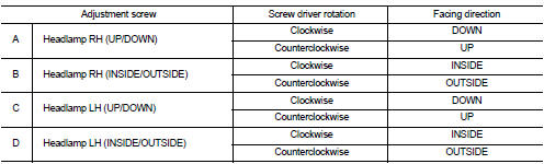
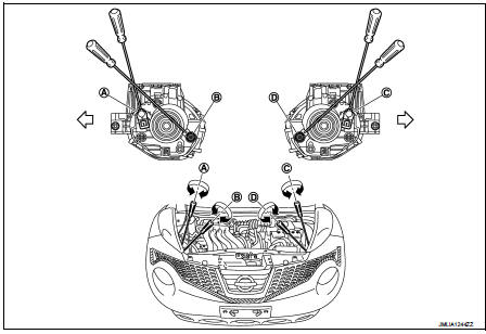
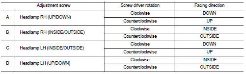
AIMING ADJUSTMENT SCREW
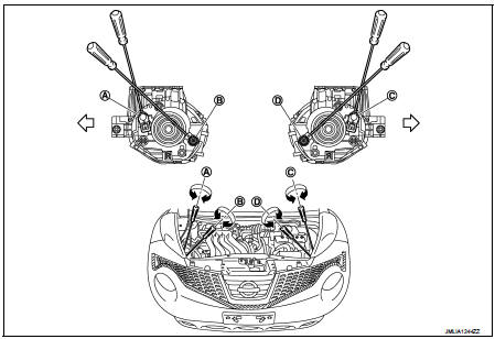
A. Headlamp RH (INSIDE/OUTSIDE)
adjustment screw
B. Headlamp RH (UP/DOWN)
adjustment screw
C. Headlamp LH (INSIDE/OUTSIDE)
adjustment screw
D. Headlamp LH (UP/DOWN)
adjustment screw
 : Vehicle center
LHD : Aiming Adjustment Procedure
1. Place the screen.
NOTE
:
ŌĆó Stop the vehicle at the perpendicular angle to the wall.
ŌĆó Set the screen so that it is perpendicular to a level load surface.
2. Face the vehicle squarely toward the screen and make the distance between the headlamp center and the screen 10 m (32.8 ft).
3. Start the engine and illuminate the headlamp (LO).
NOTE
:
Block light from the headlamp that is not being adjusted with a thick fabric or
another object, so that it
does not reach the adjustment screen.
CAUTION:
Do not cover lens surface with tape, etc. because it is made from plastic.
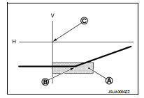
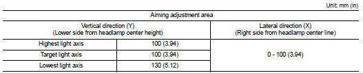
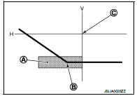
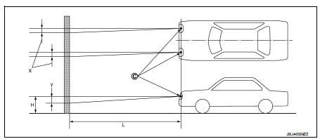
4. Use the aiming adjustment screw to adjust the elbow point projected by the low beams on the screen, so that it is within the aiming adjustment area.
Low beam distribution on the screen
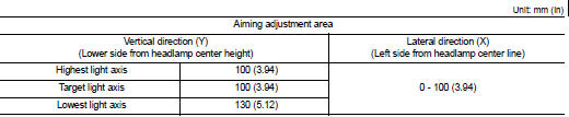
A. Aiming adjustment area
B. Elbow point
C. Headlamp center
H. Horizontal center line of headlamp
V. Vertical center line of headlamp
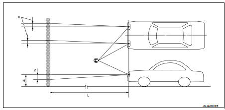
C. Vertical center line of headlamp
H. Horizontal center line of headlamp
L. Distance from headlamp center to screen
X. Aiming adjustment area
(lateral)
Y. Aiming adjustment area
(Vertical)
Distance from headlamp center to screen (L) : 10 m (32.8 ft)
RHD
RHD : Description
PREPARATION BEFORE ADJUSTING
NOTE
:
ŌĆó For details, refer to the regulations in your own country.
ŌĆó Perform aiming if the vehicle front body has been repaired and/or the headlamp assembly has been replaced.
Before performing aiming adjustment, check the following.
ŌĆó Adjust the tire pressure to the specification.
ŌĆó Fill with fuel, engine coolant and each oil.
ŌĆó Maintain the unloaded vehicle condition. (Remove luggage from the passenger compartment and the luggage room.) NOTE
:
Do not remove the temporary tire, jack and on-vehicle tool.
ŌĆó Wipe out dirt on the headlamp.
CAUTION:
Never use organic solvent (thinner, gasoline etc.)
ŌĆó Ride alone on the driver seat.
AIMING ADJUSTMENT SCREW
A. Headlamp RH (INSIDE/OUTSIDE)
adjustment screw
B. Headlamp RH (UP/DOWN)
adjustment screw
C. Headlamp LH (INSIDE/OUTSIDE)
adjustment screw
D. Headlamp LH (UP/DOWN)
adjustment screw
 : Vehicle center
RHD : Aiming Adjustment Procedure
1. Place the screen.
NOTE
:
ŌĆó Stop the vehicle at the perpendicular angle to the wall.
ŌĆó Set the screen so that it is perpendicular to a level load surface.
2. Face the vehicle squarely toward the screen and make the distance between the headlamp center and the screen 10 m (32.8 ft).
3. Start the engine and illuminate the headlamp (LO).
NOTE
:
Block light from the headlamp that is not being adjusted with a thick fabric or
another object, so that it
does not reach the adjustment screen.
CAUTION
:
Do not cover lens surface with tape, etc. because it is made from plastic.
4. Use the aiming adjustment screw to adjust the elbow point projected by the low beams on the screen, so that it is within the aiming adjustment area.
Low beam distribution on the screen
A. Aiming adjustment area
B. Elbow point
C. Headlamp center
H. Horizontal center line of headlamp
V. Vertical center line of headlamp
C. Vertical center line of headlamp
H. Horizontal center line of headlamp
L. Distance from headlamp center to screen
X. Aiming adjustment area
(lateral)
Y. Aiming adjustment area
(Vertical)
Distance from headlamp center to screen (L) : 10 m (32.8 ft)

 Front fog lamp aiming adjustment
Description
PREPARATION BEFORE ADJUSTING
NOTE:
For details, refer to the regulations in your own country.
Before performing aiming adjustment, check the following.
ŌĆó Adjust the tire pressur ...
Other materials:
Wheel alignment
Inspection
DESCRIPTION
Measure wheel alignment under unladen conditions.
NOTE:
ŌĆ£Unladen conditionsŌĆØ means that fuel, engine coolant, and lubricant are full.
Spare tire, jack, hand tools and
mats are in designated positions.
PRELIMINARY CHECK
Check the following:
ŌĆó Tires for impro ...
Back door does not opened
Diagnosis Procedure
1.CHECK BACK DOOR OPENER SWITCH
Check back door opener switch.
Refer to DLK-244, "Component Function Check".
Is the inspection result normal?
YES >> GO TO 2.
NO >> Repair or replace the malfunctioning parts.
2.CHECK BACK DOOR OPENER ACTUATOR
...
Cylinder head
Exploded View
REMOVAL
1. Cylinder head assembly
2. Cylinder head bolt
3. Washer
4. Cylinder head gasket
A.Tightening must be done following the installation procedure.
Refer to EM-209
: Always replace after every
disassembly.
: N┬Ęm (kg-m, ft-lb)
: Should be lubricated with oil.
...
