Nissan Juke Service and Repair Manual : Wheel alignment
Inspection
DESCRIPTION
Measure wheel alignment under unladen conditions.
NOTE
:
“Unladen conditions” means that fuel, engine coolant, and lubricant are full.
Spare tire, jack, hand tools and
mats are in designated positions.
PRELIMINARY CHECK
Check the following:
• Tires for improper air pressure and wear
• Road wheels for runout: refer to WT-7, "Inspection".
• Wheel bearing axial end play: refer to RAX-4, "Inspection".
• Shock absorber operation
• Each mounting point of axle and suspension for looseness and deformation
• Each of rear suspension beam and shock absorber for cracks, deformation, and
other damage
• Vehicle height (posture)
CAMBER
• Measure camber of both right and left wheels with a suitable alignment gauge.
• If camber is outside specified range, replace rear suspension beam. Refer to RSU-13, "Exploded View".
Camber : Refer to RSU-15, "Wheel Alignment".
TOE-IN
Measure toe-in by the following procedure.
WARNING:
• Always perform the following procedure on a flat surface.
• Check that no person is in front of vehicle before pushing it.
1. Bounce the front of vehicle up and down to stabilize the vehicle height (posture).
2. Push vehicle straight ahead about 5 m (16 ft).
3. Put matching mark (A) on base line of the tread (rear side) of both tires at the same height of hub center. These are measuring points.
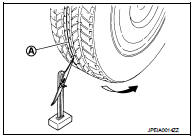
4. Measure distance (A) (rear side).
: Vehicle front
5. Push vehicle slowly ahead to rotate wheels 180 degrees (1/2 turn).
NOTE
:
If the wheels rotates more than 180 degrees (1/2 turn), start this
procedure again from the beginning. Do not push the vehicle
backward.
6. Measure distance (B) (front side).

Total toe-in = A − B Total toe-in : Refer to RSU-15, "Wheel Alignment".
• If toe-in is outside specified range, replace rear suspension beam. Refer to RSU-13, "Exploded View".
 Rear suspension assembly
Inspection
COMPONENT PART
Check the mounting conditions (looseness, backlash) of each component and
component conditions (wear,
damage) are normal.
SHOCK ABSORBER ASSEMBLY
Check for oil leaka ...

Other materials:
Diagnosis system (BCM) (with intelligent key system)
Common item
COMMON ITEM : CONSULT-III Function (BCM - COMMON ITEM)
APPLICATION ITEM
CONSULT-III performs the following functions via CAN communication with BCM.
SYSTEM APPLICATION
BCM can perform the following functions for each system.
NOTE:
It can perform the diagnosis modes except the ...
P0107, P0108 atmospheric pressure
sensor
DTC Logic
DTC DETECTION LOGIC
DTC CONFIRMATION PROCEDURE
1.PRECONDITIONING
If DTC Confirmation Procedure has been previously conducted, always perform
the following procedure
before conducting the next test.
1. Turn ignition switch OFF and wait at least 10 seconds.
2. Turn ignition swi ...
Cruise control operations
The Nissan Leaf cruise control system is designed to provide a comfortable driving experience by allowing you to maintain a set speed between 25 to 90 mph (40 to 144 km/h) without the need to keep your foot on the accelerator pedal during long stretches of road.
To activate the system ...
