Nissan Juke Owners Manual : Push-button ignition switch operation
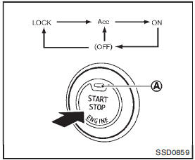
When the ignition switch is pushed without depressing the brake pedal (Continuously Variable Transmission models) or the clutch pedal (manual transmission models), the ignition switch position will change as follows: • Push once to change to ACC.
• Push two times to change to ON.
• Push three times to change to OFF.
• Push four times to return to ACC.
• Open or close any door to return to LOCK during the OFF position.
The indicator light A on the ignition switch illuminates when the ignition switch is in the ACC or ON position.
Some indicators and warnings for operation are displayed on the meter. (See “Warning/indicator lights and audible reminders” .) Continuously Variable Transmission models
The ignition lock is designed so that the ignition switch position cannot be switched to LOCK until the shift lever is moved to the P (Park) position.
When the ignition switch cannot be pushed toward the LOCK position, proceed as follows: 1. Move the shift lever into the P (Park) position.
2. Push the ignition switch to the OFF position.
3. Open the door. The ignition switch will change to the LOCK position.
The shift lever can be moved from the P (Park) position if the ignition switch is in the ON position and the brake pedal is depressed.
 Operating range for engine start function
The Intelligent Key can only be used for starting the engine when the Intelligent
Key is within the specified operating range1 .
When the Intelligent Key battery is almost discharged or strong ra ...
 Push-button ignition switch positions
LOCK (Normal parking position)
The ignition switch can only be locked in this position.
The ignition switch will be unlocked when it is pushed to the ACC position while
carrying the Intelligent Ke ...
Other materials:
Valve oil seal
VALVE OIL SEAL : Removal and Installation
REMOVAL
1. Remove camshafts. Refer to EM-78, "Exploded View".
2. Remove valve lifters. Refer to EM-78, "Exploded View".
3. Rotate crankshaft, and set piston whose valve oil seal is to be removed to
TDC. This will prevent valve
from ...
Combination switch
Exploded View
1. Combination switch
2. Combination switch connector
Removal and Installation
REMOVAL
1. Remove steering column cover. Refer to IP-13, "Removal and
Installation".
2. Remove screws.
3. Disconnect the connector.
4. Pull up the combination switch to remove it.
I ...
Anti-lock Braking System (ABS)
WARNING
While the Anti-lock Braking System (ABS) is a highly advanced safety feature, it cannot override the laws of physics or compensate for reckless and dangerous driving. The primary role of the ABS is to help the driver maintain steering control and vehicle stability during hard ...
