Nissan Juke Owners Manual : Operating range for engine start function
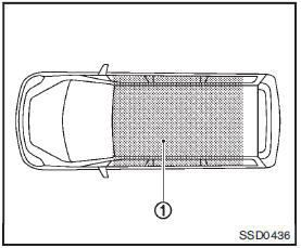
The Intelligent Key can only be used for starting the engine when the Intelligent Key is within the specified operating range1 .
When the Intelligent Key battery is almost discharged or strong radio waves are present near the operating location, the Intelligent Key system’s operating range becomes narrower and may not function properly.
If the Intelligent Key is within the operating range, it is possible for anyone, even someone who does not carry the Intelligent Key, to push the ignition switch to start the engine.
• The cargo room area is not included in the operating range but the Intelligent Key may function.
• If the Intelligent Key is placed on the instrument panel, inside the glove box or door pocket, the Intelligent Key may not function.
• If the Intelligent Key is placed near the door or window outside the vehicle, the Intelligent Key may function.
 Push-button ignition switch (models with Intelligent Key system)
WARNING
Do not operate the push-button ignition switch while driving the vehicle except
in an emergency. (The engine will stop when the ignition switch is pushed 3 consecutive
times or the igniti ...
 Push-button ignition switch operation
When the ignition switch is pushed without depressing the brake pedal (Continuously
Variable Transmission models) or the clutch pedal (manual transmission models),
the ignition switch position w ...
Other materials:
Rear Cross Traffic Alert (RCTA)
WARNING
Failure to strictly adhere to the safety warnings and operational instructions regarding the Rear Cross Traffic Alert (RCTA) system can lead to severe vehicle damage, serious personal injury, or even fatalities.
The RCTA system is a convenience feature and is not a substi ...
Engine control system symptoms
Symptom Table
SYSTEM — BASIC ENGINE CONTROL SYSTEM
1 - 6: The numbers refer to the order of inspection.
(continued on next table)
SYSTEM — ENGINE MECHANICAL & OTHER
1 - 6: The numbers refer to the order of inspection ...
System setting
Temperature Setting Trimmer
DESCRIPTION
If the temperature felt by the customer is different from the air flow
temperature controlled by the temperature
setting, the A/C auto amp. control temperature can be adjusted to compensate for
the temperature setting.
HOW TO SET
With CONSULT-III
P ...
