Nissan Juke Service and Repair Manual : Intelligent key warning buzzer
Component Function Check
1.CHECK FUNCTION
1. Select ÔÇťINTELLIGENT KEYÔÇŁ of ÔÇťBCMÔÇŁ using CONSULT-III.
2. Select ÔÇťOUTSIDE BUZZERÔÇŁ in ÔÇťACTIVE TESTÔÇŁ mode.
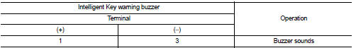
3. Check that the function operates normally according to the following conditions.
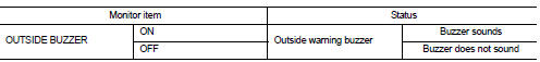
Is the inspection result normal? YES >> Intelligent Key warning buzzer is OK.
NO >> Refer to DLK-92, "Diagnosis Procedure".
Diagnosis Procedure
1.CHECK FUSE
1. Turn ignition switch OFF.
2. Check 10 A fuse, [No. 7, located in fuse block (J/B)].
Is the inspection result normal? YES >> GO TO 2.
NO >> Replace the blown fuse after repairing the affected circuit if a fuse is blown.
2.CHECK INTELLIGENT KEY WARNING BUZZER POWER SUPPLY CIRCUIT
1. Disconnect Intelligent Key warning buzzer connector.
2. Check voltage between Intelligent Key warning buzzer harness connector and ground.
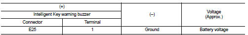
Is the inspection result normal? YES >> GO TO 3.
NO >> Repair or replace harness.
3.CHECK INTELLIGENT KEY WARNING BUZZER CIRCUIT
1. Disconnect BCM connector.
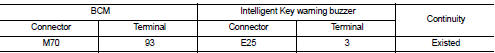
2. Check continuity between BCM harness connector and Intelligent Key warning buzzer harness connector.
3. Check continuity between BCM harness connector and ground.
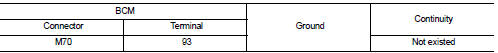
Is the inspection result normal? YES >> GO TO 4.
NO >> Repair or replace harness.
4.CHECK INTELLIGENT KEY WARNING BUZZER
Refer to DLK-93, "Component Inspection".
Is the inspection result normal? YES >> Replace BCM. Refer to BCS-93, "Removal and Installation".
NO >> Replace Intelligent Key warning buzzer.
Component Inspection
1.CHECK INTELLIGENT KEY WARNING BUZZER
1. Turn ignition switch OFF.
2. Disconnect Intelligent Key warning buzzer connector.
3. Connect battery power supply directly to Intelligent Key warning buzzer terminals and check the operation.
Is the inspection result normal? YES >> INSPECTION END
NO >> Replace Intelligent Key warning buzzer.
 Intelligent key
Component Function Check
1.CHECK FUNCTION
1. Select ÔÇťINTELLIGENT KEYÔÇŁ of ÔÇťBCMÔÇŁ using CONSULT-III.
2. Select ÔÇťRKE OPE COUN1ÔÇŁ in ÔÇťDATA MONITORÔÇŁ mode.
3. Check that the function opera ...
 Key warning lamp
Component Function Check
1.CHECK FUNCTION
1. Select ÔÇťINTELLIGENT KEYÔÇŁ of ÔÇťBCMÔÇŁ using CONSULT-III.
2. Select ÔÇťINDICATORÔÇŁ in ÔÇťACTIVE TESTÔÇŁ mode.
3. Check that the function operates n ...
Other materials:
Cylinder head
Exploded View
1. Camshaft sprocket
2. Cylinder head suspended bracket
3. Valve lifter
4. Valve rotator
5. Valve spring retainer
6. Valve spring
7. Exhaust valve
8. Intake valve
9. Valve collet
10. Cap
11. Rear engine slinger
12. Cylinder head gasket
13. Cylinder head
14. Cam ...
Precaution Necessary for Steering Wheel Rotation after Battery Disconnect
NOTE:
ÔÇó Before removing and installing any control units, first turn the ignition
switch to the LOCK position, then disconnect
both battery cables.
ÔÇó After finishing work, confirm that all control unit connectors are connected
properly, then re-connect both
battery cables.
ÔÇó Always us ...
Periodic maintenance
REAR WHEEL HUB
Inspection
COMPONENT PART
Check the mounting conditions (looseness, back lash) of each component and
component conditions (wear,
damage) are normal.
WHEEL HUB ASSEMBLY (BEARING-INTEGRATED TYPE)
Check the following items, and replace the part it necessary.
ÔÇó Move wheel h ...
