Nissan Juke Service and Repair Manual : S terminal circuit
Description
The output voltage of the alternator is controlled by the IC voltage regulator at the “S” terminal detecting the input voltage.
The “S” terminal circuit detects the battery voltage to adjust the alternator output voltage with the IC voltage regulator.
Diagnosis Procedure
1.CHECK “S” TERMINAL CONNECTION
1. Turn ignition switch OFF.
2. Check if “S” terminal is clean and tight.
Is the inspection result normal? YES >> GO TO 2.
NO >> Repair “S” terminal connection.
2.CHECK “S” TERMINAL CIRCUIT
Check voltage between alternator harness connector and ground
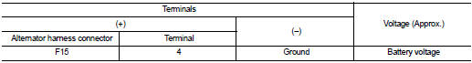
Is the inspection result normal? YES >> Refer to CHG-12, "GASOLINE ENGINE MODELS : Work Flow".
NO >> Check harness for open between alternator and fuse.
 L terminal circuit (short)
Description
The “L” terminal circuit controls the charge warning lamp. The charge warning
lamp illuminates when the ignition
switch is set to ON or START. When the alternator is providing suff ...
 Symptom diagnosis
CHARGING SYSTEM
Symptom Table
...
Other materials:
B2321, B2322 oil level sensor
Description
The oil level sensor detects the level of engine oil, and then transmits the
oil level signal to the combination
meter.
DTC Logic
DTC DETECTION LOGIC
NOTE:
When the following conditions are satisfied, the combination meter reads the
resistance value of oil level sensor.
Th ...
B1051, B1056 driver air bag module
DTC Logic
DTC DETECTION LOGIC
DTC CONFIRMATION PROCEDURE
1.CHECK SELF-DIAG RESULT
With CONSULT-III
1. Turn ignition switch ON.
2. Perform “Self Diagnostic Result” mode of “AIR BAG” using CONSULT-III.
Without CONSULT-III
1. Turn ignition switch ON.
2. Check the air bag warning la ...
Brake assist
When the force applied to the brake pedal exceeds a certain level, the Brake
Assist is activated generating greater braking force than a conventional brake booster
even with light pedal force.
WARNING
The Brake Assist is only an aid to assist braking operation and is not a collision
warning ...
