Nissan Juke Service and Repair Manual : B2321, B2322 oil level sensor
Description
The oil level sensor detects the level of engine oil, and then transmits the oil level signal to the combination meter.
DTC Logic
DTC DETECTION LOGIC
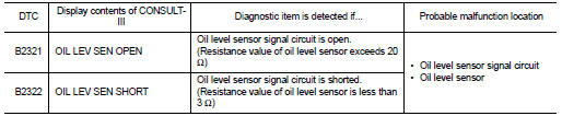
NOTE
:
When the following conditions are satisfied, the combination meter reads the
resistance value of oil level sensor.
The combination meter does not read the oil level sensor resistance value within 5 minutes after the previous reading of oil level sensor resistance value by the combination meter.
1. Turn the ignition switch OFF.
2. Wait for 5 minutes or more, then open the front door.
DTC (B2321: OIL LEV SEN OPEN, B2322: OIL LEV SEN SHORT) is also detected at the timing described above.
Diagnosis Procedure
1.CHECK OIL LEVEL SENSOR SIGNAL CIRCUIT
1. Turn ignition switch OFF.
2. Disconnect connectors of combination meter and oil level sensor.
3. Check for continuity between combination meter harness connector and oil level sensor harness connector.
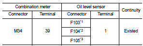
*1: HR16DE engine models *2: MR16DDT engine models *3: K9K engine models
4. Check for continuity between combination meter harness connector and ground.
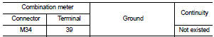
Is the inspection result normal? YES >> GO TO 2.
NO >> Repair harnesses or connectors.
2.CHECK OIL LEVEL SENSOR GROUND CIRCUIT
Check for continuity between combination meter harness connector and oil level sensor harness connector.
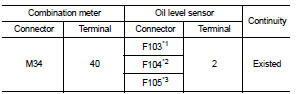
*1: HR16DE engine models *2: MR16DDT engine models *2: K9K engine models
Is the inspection result normal? YES >> INSPECTION END
NO >> Repair harnesses or connectors.
Component Inspection
1.CHECK OIL LEVEL SENSOR
1. Turn ignition switch OFF.
2. Disconnect oil level sensor connector.
3. Check resistance between oil level sensor terminals 1 and 2.
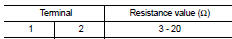
Is the inspection result normal? YES >> INSPECTION END
NO >> Replace oil level sensor.
 B2268 water temp
Description
The engine coolant temperature signal is transmitted from ECM to the
combination meter via CAN communication.
DTC Logic
DTC DETECTION LOGIC
Diagnosis Procedure
1.PERFORM SELF-DIAG ...
 Power supply and ground circuit
Combination meter
COMBINATION METER : Diagnosis Procedure
1.CHECK FUSE
Check for blown fuses.
Is the inspection result normal?
YES >> GO TO 2.
NO >> Be sure to eliminate cause of ...
Other materials:
Intelligent Key operating range
The Intelligent Key functions can only be used when the Intelligent Key is within
the specified operating range from the request switch 1 .
When the Intelligent Key battery is discharged or strong radio waves are present
near the operating location, the Intelligent Key system’s operating ra ...
Garage Jack and Safety Stand and 2-Pole Lift
WARNING:
• Park the vehicle on a level surface when using the jack. Check to avoid
damaging pipes, tubes, etc.
under the vehicle.
• Never get under the vehicle while it is supported only by the jack. Always use
safety stands when
you have to get under the vehicle.
• Place wheel choc ...
Water pump
Exploded View
1. Gasket
2. Water pump
3. Water pump pulley
: Always replace after every
disassembly.
: N·m (kg-m, in-lb)
: N·m (kg-m, ft-lb)
Removal and Installation
REMOVAL
1. Drain engine coolant from radiator. Refer to CO-37, "Draining".
CAUTION:
• Perform this st ...
