Nissan Juke Service and Repair Manual : Water pump
Exploded View
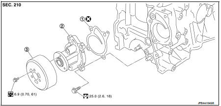
1. Gasket
2. Water pump
3. Water pump pulley
 : Always replace after every
disassembly.
 : N┬Ęm (kg-m, in-lb)
 : N┬Ęm (kg-m, ft-lb)
Removal and Installation
REMOVAL
1. Drain engine coolant from radiator. Refer to CO-37, "Draining".
CAUTION:
ŌĆó Perform this step when the engine is cold.
ŌĆó Never spill engine coolant on drive belt.
2. Steer front wheel to the right.
3. Remove front fender protector (RH). Refer to EXT-22, "Removal and Installation".
4. Loosen mounting bolts of water pump pulley before loosening belt tension of drive belt.
5. Remove drive belt. Refer to EM-160, "Removal and Installation".
6. Remove water pump pulley.
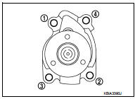
7. Remove water pump.
ŌĆó Loosen mounting bolts in reverse order as shown in the figure.
ŌĆó Engine coolant will leak from cylinder block, so have a receptacle ready below.
CAUTION:
ŌĆó Handle water pump vane so that it does not contact any
other parts.
ŌĆó Water pump cannot be disassembled and should be replaced as a unit.
INSTALLATION
Install in the reverse order of removal.
Inspection
INSPECTION AFTER REMOVAL
ŌĆó Check visually that there is no significant dirt or rusting on water pump body and vane (A).
ŌĆó Check that there is no looseness in vane shaft, and that it turns smoothly when rotated by hand.
ŌĆó Replace water pump, if necessary.
INSPECTION AFTER INSTALLATION
ŌĆó Check for leakage of engine coolant using the radiator cap tester adapter (commercial service tool) and the radiator cap tester (commercial service tool). Refer to CO-37, "Inspection".
ŌĆó Start and warm up the engine. Check visually that there is no leakage of engine coolant.
 Cooling fan
Exploded View
1. Fan motor
2. Fan shroud
3. Cooling fan
A. Apply on fan motor shaft
: Apply genuine high strength
thread locking sealant or equivalent.
: N┬Ęm (kg-m, in-lb)
Removal and I ...
 Thermostat
Exploded View
1. Radiator hose (upper)
2. Water inlet
3. Rubber ring
4. Thermostat
A. To radiator
: Always replace after every
disassembly.
: N┬Ęm (kg-m, ft-lb)
Removal and Installation
...
Other materials:
Towing recommended by NISSAN
Two-Wheel Drive (2WD) models
NISSAN recommends that your vehicle be towed with the driving (front) wheels
off the ground or place the vehicle on a flat bed truck as illustrated.
CAUTION
ŌĆó Never tow CVT models with the front wheels on the ground or four wheels
on the ground (forward ...
Precaution
Precaution for Supplemental Restraint System (SRS) "AIR BAG" and "SEAT
BELT
PRE-TENSIONER"
The Supplemental Restraint System such as ŌĆ£AIR BAGŌĆØ and ŌĆ£SEAT BELT PRE-TENSIONERŌĆØ,
used along
with a front seat belt, helps to reduce the risk or severity of injury to the
...
Precaution Necessary for Steering Wheel Rotation after Battery Disconnect
NOTE:
ŌĆó Before removing and installing any control units, first turn the ignition
switch to the LOCK position, then disconnect
both battery cables.
ŌĆó After finishing work, confirm that all control unit connectors are connected
properly, then re-connect both
battery cables.
ŌĆó Always us ...
