Nissan Juke Service and Repair Manual : Thermostat
Exploded View
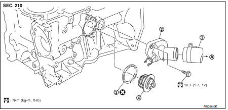
1. Radiator hose (upper)
2. Water inlet
3. Rubber ring
4. Thermostat
A. To radiator
 : Always replace after every
disassembly.
 : N·m (kg-m, ft-lb)
Removal and Installation
REMOVAL
1. Drain engine coolant from radiator. Refer to CO-37, "Draining".
CAUTION:
Perform this step when engine is cold.
2. Remove air duct (inlet). Refer to EM-161, "Removal and Installation".
3. Disconnect radiator hose (lower) from water inlet. Refer to CO-42, "Exploded View".
4. Remove water inlet and thermostat.
• Engine coolant leakage from cylinder block, so have a receptacle ready below.
INSTALLATION
Note the following, and install in the reverse order of removal.
Thermostat
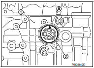
• Install thermostat with making rubber ring (1) groove fit to thermostat
flange (A) with the whole circumference.
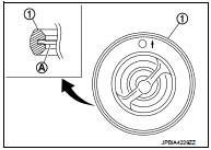
• Install thermostat (2) with jiggle valve (A) facing upwards.
1 : Cylinder block
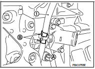
Water InletWater Inlet After installation, fix water inlet clip (A) on the oil level gauge guide (1) as shown in the figure.
After installation, fix water inlet clip (A) on the oil level gauge guide (1) as shown in the figure.
B : Positioning
Inspection
INSPECTION AFTER REMOVAL
Thermostat
• Place a thread (A) so that it is caught in the valves of thermostat
(1). Immerse fully in a container (B) filled with water. Heat while
stirring.
• The valve opening temperature is the temperature at which the valve opens and falls from the thread.
• Continue heating. Check the full open valve lift amount.
• After checking the maximum valve lift amount, lower the water temperature and check the valve closing temperature.
Standard: Refer to CO-54, "Thermostat".
• If out of the standard, replace thermostat.
INSPECTION AFTER INSTALLATION
• Check for leakage of engine coolant using the radiator cap tester adapter (commercial service tool) and the radiator cap tester (commercial service tool). Refer to CO-37, "Inspection".
• Start and warm up the engine. Check visually that there is no leakage of engine coolant.
 Water pump
Exploded View
1. Gasket
2. Water pump
3. Water pump pulley
: Always replace after every
disassembly.
: N·m (kg-m, in-lb)
: N·m (kg-m, ft-lb)
Removal and Installation
REMOVAL
1. Drain ...
 Water outlet
Exploded View
1. Engine coolant temperature sensor
2. Clamp
3. Gasket
4. Clamp
5. Bracket
6. Clamp
7. Water outlet
8. Clamp
9. Clamp
10. Washer
A. To electric throttle control actua ...
Other materials:
Door mirror remote control switch
Exploded View
1. Instrument lower panel
2. Switch bracket
3. Door mirror remote control switch
Removal and Installation
REMOVAL
1. Remove the instrument lower panel. Refer to IP-13, "Removal and
Installation".
2. Remove mounting screws and remove switch bracket from instrument ...
P1740 select solenoid
DTC Logic
DTC DETECTION LOGIC
DTC CONFIRMATION PROCEDURE
CAUTION:
Always drive vehicle at a safe speed.
NOTE:
If “DTC CONFIRMATION PROCEDURE” has been previously performed, always turn
ignition switch
OFF and wait at least 10 seconds before performing the next test.
After the repai ...
Meters and gauges
1. Tachometer
2. Engine coolant temperature gauge
3. Vehicle information display
— Odometer/twin trip odometer
— Trip computer
— Torque vectoring AWD (AWD model)
— Outside air temperature
4. Fuel gauge
5. Speedometer
6. Warning/indicator lights
7. Instrument brightness ...
