Nissan Juke Service and Repair Manual : Blower fan on signal
Component Function Check
1.CHECK BLOWER FAN ON SIGNAL
 With CONSULT-III
1. Turn ignition switch ON.
2. Select “AIR CONDITIONER” of “BCM” using CONSULT-III.
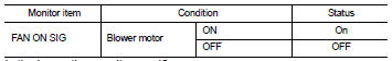
3. Select “FAN ON SIG” in “DATA MONITOR” mode.
4. Check blower fan ON signal when the fan control dial is operated.
Is the inspection result normal? YES >> INSPECTION END
NO >> Refer to HAC-77, "Diagnosis Procedure".
Diagnosis Procedure
1.CHECK BLOWER FAN ON SIGNAL
1. Turn ignition switch OFF.
2. Disconnect A/C auto amp. harness connector.
3. Turn ignition switch ON.
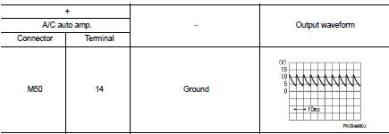
4. Check output waveform between A/C auto amp. and ground with using oscilloscope
Is the inspection result normal? YES >> Replace A/C auto amp. Refer to HAC-91, "Removal and Installation".
NO >> GO TO 2.
2.CHECK BLOWER FAN ON SIGNAL CIRCUIT FOR OPEN
1. Turn ignition switch OFF.
2. Disconnect BCM connector.
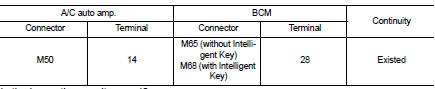
3. Check continuity A/C auto amp. harness connector and BCM harness connector.
Is the inspection result normal? YES >> GO TO 3.
NO >> Repair harness or connector.
3.CHECK BLOWER FAN ON SIGNAL CIRCUIT FOR SHORT
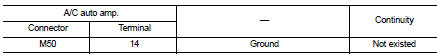
Check continuity between A/C auto amp. harness connector and ground.
Is the inspection result normal? YES >> Replace BCM. Refer to BCS-93, "Removal and Installation" (with Intelligent Key) or BCS-161, "Removal and Installation" (without Intelligent Key).
NO >> Repair harness or connector
 A/C on signal
Component Function Check
1.CHECK A/C ON SIGNAL
With CONSULT-III
1. Turn ignition switch ON.
2. Operate blower motor.
3. Select “AIR CONDITIONER” of “BCM” using CONSULT-III.
4. Select “ ...
 Blower motor
Diagnosis Procedure
1.CHECK FUSE
1. Turn ignition switch OFF.
2. Check following fuses.
- 10A fuse [No. 15, located in fuse block (J/B)]
- 15A fuses [Nos. 14 and 16, located in fuse block (J/B) ...
Other materials:
Component parts
Component Parts Location
LHD models
1. ABS actuator and electric unit (control
unit)
Refer to BRC-97, "Component Parts
Location".
2. ECM
Refer to EC-25, "ENGINE CONTROL
SYSTEM :
Component Parts Location".
3. Front wheel sensor
Refer to BRC-97, "Component Parts
...
For frontal collision : When SRS is not activated in a collision
CAUTION:
Due to varying models and option levels, not all parts listed in the chart below
apply to all vehicles.
WORK PROCEDURE
1. Before performing any of the following steps, ensure that all vehicle body
and structural repairs have been
completed.
2. Check the SRS components using the t ...
Diagnosis system (combination meter)
On Board Diagnosis Function
ON BOARD DIAGNOSIS ITEM
The combination meter allows the following diagnosis items with the on-board
diagnosis function.
METHOD OF STARTING
1. Turn ignition switch ON, and switch the trip meter to “trip A” or “trip
B”.
2. Turn ignition switch OFF.
3. W ...
