Nissan Juke Service and Repair Manual : Consult-III/GST checking system
Description
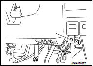
• When CONSULT-III/GST is connected with a data link connector (A) equipped on the vehicle side, it will communicate with the control unit equipped in the vehicle and then enable various kinds of diagnostic tests.
1 : Instrument lower panel RH
• Refer to CONSULT-III Software Operation Manual for more information.
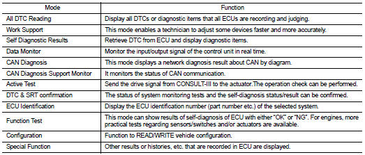
Consult-III Function and System Application*1
FUNCTION
SYSTEM APPLICATION*1
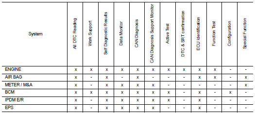
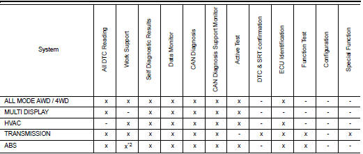
x: Applicable
*1 : If GST application is equipped, functions in accordance with SAE J1979 and
ISO 15031-5 can be used.
*2: With ESP models
Consult-III/GST Data Link Connector (DLC) Circuit
INSPECTION PROCEDURE
If the CONSULT-III/GST cannot diagnose the system properly, check the following items.
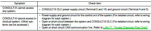
NOTE:
The DDL1 and DDL2 circuits from DLC pins 12, 13, 14 and 15 may be connected to more than one system. A short in a DDL circuit connected to a control unit in one system may affect CONSULT-III access to other systems.
If the GST cannot operate properly, check the circuit based on the information of SAE J1962 and ISO 15031- 3.
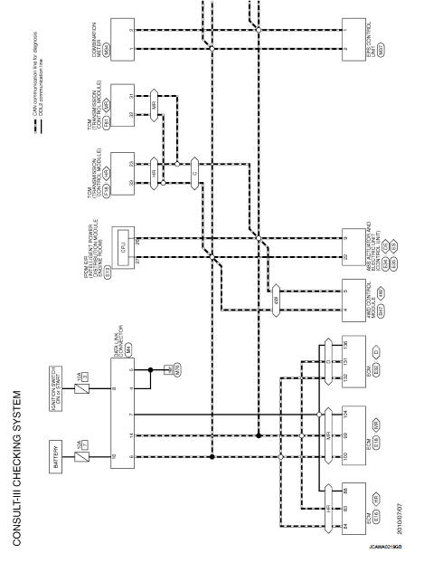
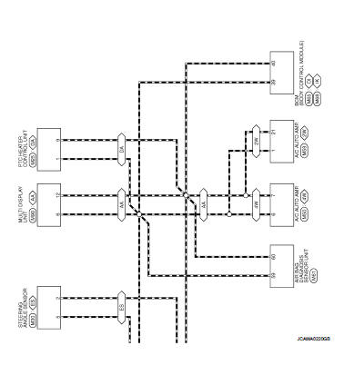
Wiring Diagram - Consult-III/GST checking system -
For connector terminal arrangements, harness layout, and alphabets in a
 (option abbreviation; if not
described in wiring diagram), refer to GI-12, "Connector Information/Explanation
of Option Abbreviation"
 Service information for electrical incident
Work Flow
WORK FLOW
Control Units and Electrical Parts
PRECAUTIONS
• Never reverse polarity of battery terminals.
• Install only parts specified for a vehicle.
• Before replacing the c ...
 Inspection and adjustment
ADDITIONAL SERVICE WHEN REMOVING BATTERY NEGATIVE TERMINAL
ADDITIONAL SERVICE WHEN REMOVING BATTERY NEGATIVE TERMINAL : Required
Procedure After Battery Disconnection
*: Not equipped. ...
Other materials:
C1140 actuator relay system
DTC Logic
DTC DETECTION LOGIC
DTC CONFIRMATION PROCEDURE
1.PRECONDITIONING
If “DTC CONFIRMATION PROCEDURE” has been previously conducted, always turn
ignition switch OFF and
wait at least 10 seconds before conducting the next test.
>> GO TO 2.
2.CHECK DTC DETECTION
With CON ...
Thermo control amplifier
Removal and Installation
REMOVAL
1. Remove evaporator. Refer to HA-115, "EVAPORATOR : Removal and
Installation".
2. Remove thermo control amp. from evaporator.
INSTALLATION
Note the following items, and then install in the reverse order of removal.
CAUTION:
• Replace O-ring ...
Break-in schedule
CAUTION
During the first 1,200 miles (2,000 km), follow these recommendations to obtain
maximum engine performance and ensure the future reliability and economy of your
new vehicle. Failure to follow these recommendations may result in shortened engine
life and reduced engine performance.
†...
