Nissan Juke Service and Repair Manual : Seat belt buckle switch signal circuit (driver side)
Component Function Check
1.CHECK COMBINATION METER INPUT SIGNAL
Select the “Data Monitor” for the “METER/M&A” and check the “BUCKLE SW” monitor value.
BUCKLE SW
When driver seat belt is fastened : Off
When driver seat belt is unfastened : On
>> INSPECTION END
Diagnosis Procedure
1.CHECK SEAT BELT BUCKLE SWITCH (DRIVER SIDE) CIRCUIT
1. Turn ignition switch OFF.
2. Disconnect combination meter connector and seat belt buckle switch (driver side) connector.
3. Check continuity between combination meter harness connector and seat belt buckle switch (driver side) harness connector.
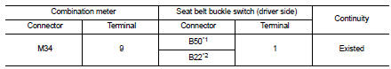
*1: LHD models
*2: RHD models
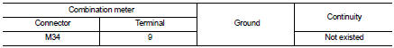
4. Check harness continuity between combination meter harness connector and ground.
Is the inspection result normal? YES >> GO TO 2.
NO >> Repair harness or connector.
2.CHECK SEAT BELT BUCKLE SWITCH (DRIVER SIDE) GROUND CIRCUIT
Check harness continuity between seat belt buckle switch (driver side) harness connector and ground.
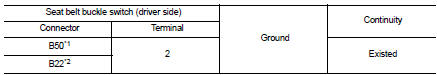
*1: LHD models
*2: RHD models
Is the inspection result normal? YES >> INSPECTION END
NO >> Repair harness or connector.
Component Inspection
1.CHECK SEAT BELT BUCKLE SWITCH UNIT
1. Turn ignition switch OFF.
2. Disconnect the seat belt buckle switch (driver side) connector.
3. Check continuity between terminals.
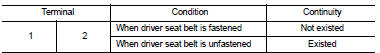
Is the inspection result normal? YES >> INSPECTION END
NO >> Replace the seat belt buckle (driver side). Refer to SB-8, "SEAT BELT BUCKLE : Removal and Installation".
 Oil pressure switch signal circuit
Component Function Check
1.CHECK COMBINATION METER INPUT SIGNAL
Select the “Data Monitor” for the “METER/M&A” and check the “OIL W/L” monitor
value.
“OIL W/L”
Ignition switch ...
 Seat belt buckle switch signal circuit (passenger side)
Diagnosis Procedure
1.CHECK SEAT BELT BUCKLE SWITCH (PASSENGER SIDE) CIRCUIT
1. Turn ignition switch OFF.
2. Disconnect combination meter connector and seat belt buckle switch (passenger
side) co ...
Other materials:
Oil filter
Exploded View
1. O-ring
2. Oil filter bracket
3. Oil pressure switch
4. Oil filter
5. O-ring
6. Connecting bolt
A. To oil cooler
: N·m (kg-m, ft-lb)
: Always replace after every
disassembly.
Removal and Installation
REMOVAL
1. Using an oil filter wrench [SST:KV113C0010 (Mot.1329 ...
Precaution
Precaution for Supplemental Restraint System (SRS) "AIR BAG" and "SEAT
BELT
PRE-TENSIONER"
The Supplemental Restraint System such as “AIR BAG” and “SEAT BELT PRE-TENSIONER”,
used along
with a front seat belt, helps to reduce the risk or severity of injury to the
...
LED Daytime Running Lights (DRL) system (Type A)
The LED Daytime Running Lights (DRL) on your Nissan Leaf are designed for enhanced visibility, automatically illuminating at 100% intensity whenever the power switch is in the READY to drive position, provided the parking brake has been fully released.
The LED DRL system remains activ ...
