Nissan Juke Service and Repair Manual : Seat belt buckle switch signal circuit (passenger side)
Diagnosis Procedure
1.CHECK SEAT BELT BUCKLE SWITCH (PASSENGER SIDE) CIRCUIT
1. Turn ignition switch OFF.
2. Disconnect combination meter connector and seat belt buckle switch (passenger side) connector.
3. Check continuity between combination meter harness connector and seat belt buckle switch (passenger side) harness connector.
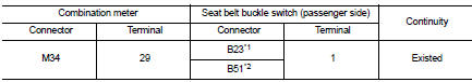
*1: RHD models
*2: LHD models
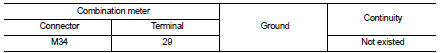
4. Check harness continuity between combination meter harness connector and ground.
Is the inspection result normal? YES >> GO TO 2.
NO >> Repair harness or connector.
2.CHECK SEAT BELT BUCKLE SWITCH (PASSENGER SIDE) GROUND CIRCUIT
Check harness continuity between seat belt buckle switch (passenger side) harness connector and ground.
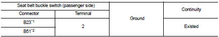
*1: RHD models
*2: LHD models
Is the inspection result normal? YES >> INSPECTION END
NO >> Repair harness or connector.
Component Inspection (Seat Belt Buckle Switch)
1.CHECK SEAT BELT BUCKLE SWITCH (PASSENGER SIDE)
1. Turn ignition switch OFF.
2. Disconnect the seat belt buckle switch (passenger side) connectors.
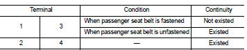
3. Check continuity between terminals.
Is the inspection result normal? YES >> INSPECTION END
NO >> Replace the seat belt buckle (passenger side). Refer to SB-8, "SEAT BELT BUCKLE : Removal and Installation".
Component Inspection (Occupant Detection Unit)
1.CHECK OCCUPANT DETECTION UNIT
1. Turn ignition switch OFF.
2. Disconnect the occupant detection unit connector.
3. Check continuity between terminals.
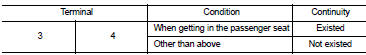
Is the inspection result normal? YES >> INSPECTION END
NO >> Replace the seat cushion trim and pad. Refer to SE-21, "SEAT CUSHION : Disassembly and Assembly" (2WD) or SE-29, "SEAT CUSHION : Disassembly and Assembly" (4WD).
 Seat belt buckle switch signal circuit (driver side)
Component Function Check
1.CHECK COMBINATION METER INPUT SIGNAL
Select the “Data Monitor” for the “METER/M&A” and check the “BUCKLE SW”
monitor value.
BUCKLE SW
When driver seat ...
 A/C auto AMP. Connection recognition signal circuit
Diagnosis Procedure
1.CHECK A/C AUTO AMP. CONNECTION RECOGNITION SIGNAL
1. Turn ignition switch ON.
2. Check voltage between combination meter harness connector and ground.
Is the inspection res ...
Other materials:
System Temporarily Unavailable
When the advanced safety sensors detect radar blockage, the Nissan Leaf safety suite will automatically deactivate affected systems to ensure reliability. These features will remain unavailable until the environmental conditions clear and the sensors can once again accurately monitor the vehicle's s ...
P1745 line pressure control
Description
The line pressure solenoid valve regulates the oil pump discharge pressure to
suit the driving condition in
response to a signal sent from the TCM.
DTC Logic
DTC DETECTION LOGIC
DTC CONFIRMATION PROCEDURE
NOTE:
If “DTC CONFIRMATION PROCEDURE” has been previously performed, ...
ASCD main switch
Component Function Check
1.CHECK ASCD MAIN SWITCH FUNCTION
With CONSULT-III
1. Turn ignition switch ON.
2. Select “MAIN SW” in “DATA MONITOR” mode of “ENGINE” using CONSULT-III.
3. Check “MAIN SW” indication as per the following condition.
Without CONSULT-III
1. Turn ignitio ...
