Nissan Juke Service and Repair Manual : Rear door finisher
Exploded View
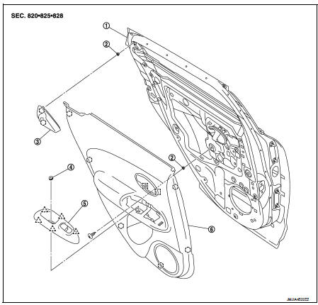
1. Rear door panel
2. Grommet
3. Rear door corner cover inner
4. Cap
5. Power window switch finisher
6. Rear door finisher
 : Clip
 : Pawl
 : Metal clip
Removal and Installation
REMOVAL
CAUTION:
• When removing, always use a remover tool that is made of plastic.
• Never damage the door panel.
1. Fully open door window.
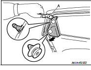
2. Remove rear corner cover inner.
Disengage rear corner cover inner fixing clips with a remover tool.
 : Clip
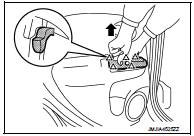
3. Remove power window switch finisher and power window switch as a unit.
1. Pull up power window switch finisher and power window switch as a unit to disengage the fixing pawls.
 : Pawl
2. Disconnect harness connector, and then remove power window switch finisher and power window switch as a unit.
4. Remove rear door finisher fixing screw.
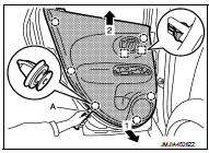
5. Remove rear door finisher.
1. Disengage rear door finisher fixing clips and metal clips with a remover tool (A).
 : Clip
 : Metal clip
2. Pull toward the direction of the arrows as shown in the figure to remove.
CAUTION:
Insert a remover tool between body side panel and clip and
disengage pawl
NOTE
:
Remove power window switch. Refer to PWC-44, "Removal and Installation".
INSTALLATION
Note the following item, and install in the reverse order of removal.
CAUTION:
When installing rear door finisher, check that clips, and metal clips are
securely in body panel holes,
and press them in.
 Front door finisher
Exploded View
LHD models
1. Front door panel
2. Front door finisher
3. Cap
4. Pull handle
5. Power window switch finisher
6. Pull handle bracket
: Clip
: Pawl
: Metal clip
Removal and ...
 Body side trim
Exploded View
1. Rear body side welt
2. Center pillar upper garnish
3. Front body side welt
4. Front pillar garnish
5. Metal clip
6. Dash side finisher
7. Harness clip
8. Front kicking ...
Other materials:
P0340 CMP sensor (PHASE)
DTC Logic
DTC DETECTION LOGIC
DTC CONFIRMATION PROCEDURE
1.PRECONDITIONING
If DTC Confirmation Procedure has been previously conducted, always perform
the following procedure
before conducting the next test.
1. Turn ignition switch OFF and wait at least 10 seconds.
2. Turn ignition swit ...
Door lock actuator
Driver side
DRIVER SIDE : Component Function Check
1.CHECK FUNCTION
1. Select “DOOR LOCK” of “BCM” using CONSULT-III.
2. Select “DOOR LOCK” in “ACTIVE TEST” mode.
3. Check that the function operates normally according to the following
conditions.
Is the inspection result no ...
Compressor
Exploded View
REMOVAL
1. High-pressure flexible hose
2. O-ring
3. Compressor
4. O-ring
5. Low-pressure flexible hose
A. To condenser
B. To evaporator
: N·m (kg-m, ft-lb)
DISASSEMBLY
1. Compressor unit
2. Field coil
3. Snap ring
4. Pulley assembly
5. Snap ring
6. Shim
7. ...
