Nissan Juke Service and Repair Manual : Body side trim
Exploded View
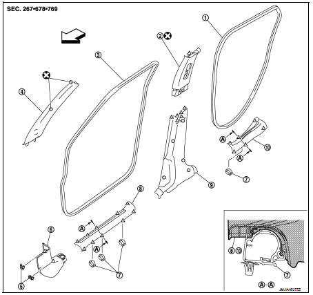
1. Rear body side welt
2. Center pillar upper garnish
3. Front body side welt
4. Front pillar garnish
5. Metal clip
6. Dash side finisher
7. Harness clip
8. Front kicking plate inner
9. Center pillar lower garnish
10. Rear kicking plate inner
 : Clip
 : Pawl
 : Metal clip
 : Vehicle front
 : Do not reuse
Front pillar garnish : Removal and Installation
REMOVAL
CAUTION
:
• When removing, always use a remover tool that is made of plastic.
• Never damage the body.
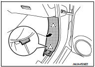
1. Release front pillar garnish portion of front body side welt.
2. Remove front pillar garnish.
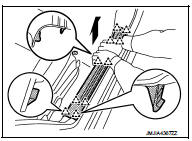
1. Disengage front pillar garnish fixing clips with a remover tool (A).
 : Clip
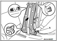
2. Twist clip portion of front pillar garnish using long nose pliers while pulling upper side of front pillar garnish toward inside, and then remove clip from front pillar garnish side.
3. Remove front pillar garnish of pull toward the arrow direction.
INSTALLATION
Note the following items, and install in the reverse order of removal.
CAUTION:
• When installing front pillar garnish, check that clips are securely in body
panel holes, and press
them in.
• Replace front pillar garnish with a new part after removal. Never reuse front pillar garnish.
Kicking plate inner : Removal and Installation
REMOVAL
CAUTION:
Never damage the body.
FRONT KICKING PLATE INNER
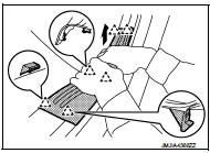
Pull up front kicking plate inner, and then disengage the pawls.
 : Pawl
REAR KICKING PLATE INNER
Pull up rear kicking plate inner, and then disengage the pawls.
 : Pawl
INSATALLATION
Install in the reverse order of removal.
Dash side finisher : Removal and Installation
REMOVAL
CAUTION:
Never damage the body.
1. Remove front kicking plate inner. Refer to INT-19, "KICKING PLATE INNER : Removal and Installation".
2. Pull back dash side finisher, and then disengage the pawls.
 : Pawl
3. Disconnect dash side finisher, vehicle front side, from stud bolt and remove dash side finisher.
INSTALLATION
Install in the reverse order of removal.
Body side welt : Removal and Instal
REMOVAL
CAUTION:
• Never excessively pull body side welt.
• Never damage the body.
FRONT BODY SIDE WELT
1. Remove front kicking plate inner. Refer to INT-19, "KICKING PLATE INNER : Removal and Installation".
2. Remove front body side welt.
REAR BODY SIDE WELT
1. Remove rear kicking plate inner. Refer to INT-19, "KICKING PLATE INNER : Removal and Installation".
2. Remove rear body side welt.
INSTALLATION
Install in the reverse order of removal.
Center pillar lower garnish : Removal and Installation
REMOVAL
CAUTION:
• When removing, always use a remover tool that is made of plastic.
• Never damage the body.
1. Fully open front door and rear door.
2. Slide front seat to the fully forward position. Tilt seatback forward.
3. Remove Front body side welt and rear body side welt. Refer to INT-20, "BODY SIDE WELT : Removal and Installation".
4. Disengage center pillar lower garnish fixing clips and pawls with a remover tool (A), and then remove center pillar lower garnish.
 : Clip
 : Pawl
INSTALLATION
Note the following item, and install in the reverse order of removal.
CAUTION:
When installing center pillar lower garnish, check that clips are securely in
body panel holes, and
press them in.
Center pillar upper garnish : Removal and Installation
REMOVAL
CAUTION:
• When removing, always use a remover tool that is made of plastic.
• Never damage the body.
1. Remove center pillar lower garnish. Refer to INT-20, "CENTER PILLAR LOWER GARNISH : Removal and Installation".
2. Remove front seat belt shoulder anchor. Refer toSB-5, "SEAT BELT RETRACTOR : Removal and Installation".
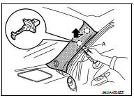
3. Disengage center pillar upper garnish lower side fixing pawl.
 : Pawl
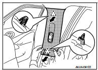
4. Disengage center pillar upper garnish upper side fixing clip.
NOTE
:
Removal operation can be performed easily when pressing pawl by inserting a
removal tool from direction
(A) as shown in the figure.
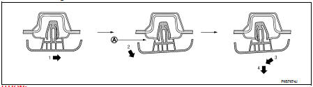
CAUTION:
Be careful not to apply excessive force when removing center pillar upper
garnish. Otherwise,
pawl may be damaged and fragments may drop in panel holes on body.
Note the following items, and install in the reverse order of removal.
CAUTION:
• Replace center pillar upper garnish with a new part after removal. Never reuse
center pillar upper
garnish.
• When installing center pillar upper garnish, check that pawls are securely in body panel holes, and press them in.
 Rear door finisher
Exploded View
1. Rear door panel
2. Grommet
3. Rear door corner cover inner
4. Cap
5. Power window switch finisher
6. Rear door finisher
: Clip
: Pawl
: Metal clip
Removal and Installa ...
 Floor trim
Exploded View
LHD models
1. Floor carpet
2. Carpet hook
3. Trim clip
4. Column hole cover
5. Harness clip
6. Front floor spacer RH
7. Front floor spacer LH
8. Rear floor spacer LH
9. ...
Other materials:
Service
• Never use electrical test equipment to check SRS circuits unless instructed
to in this Service Manual.
• Before servicing the SRS, turn ignition switch OFF, disconnect battery
negative terminal and wait at least 3
minutes.
For approximately 3 minutes after the battery negative termina ...
P061A ECM
DTC Logic
DTC DETECTION LOGIC
Diagnosis Procedure
1.INSPECTION START
1. Turn ignition switch ON.
2. Erase DTC.
3. Turn ignition switch OFF and wait for 20 seconds.
4. Turn ignition switch ON and perform the self-diagnosis.
Is the DTC P061A displayed again?
YES >> GO TO 2.
NO &g ...
Wiring diagram
SECURITY CONTROL SYSTEM
LHD
LHD : Wiring Diagram
For connector terminal arrangements, harness layouts, and alphabets in a
(option abbreviation; if not
described in wiring diagram), refer to GI-12, "Connector Information/Explanation
of Option Abbreviation".
RHD
RHD : Wiring D ...
