Nissan Juke Service and Repair Manual : Floor trim
Exploded View
LHD models
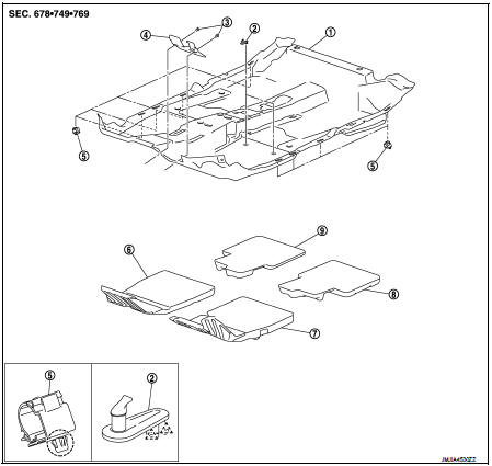
1. Floor carpet
2. Carpet hook
3. Trim clip
4. Column hole cover
5. Harness clip
6. Front floor spacer RH
7. Front floor spacer LH
8. Rear floor spacer LH
9. Rear floor spacer RH
 : Clip
 : Pawl
Removal and Installation
REMOVAL
CAUTION:
ŌĆó When removing, always use a remover tool that is made of plastic.
ŌĆó Never damage the body.
1. Remove front seat assembly (LH and RH).
ŌĆó 2WD models: Refer to SE-19, "Removal and Installation".
ŌĆó 4WD models: Refer to SE-27, "Removal and Installation".
2. Remove rear seat cushion.
ŌĆó 2WD models: Refer to SE-33, "SEAT CUSHION : Removal and Installation".
ŌĆó 4WD models: Refer to SE-42, "SEAT CUSHION : Removal and Installation".
3. Remove center console assembly. Refer to IP-23, "Removal and Installation".
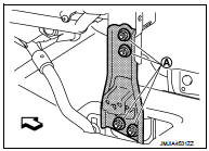
4. Remove instrument stay.
Remove instrument stay mounting nuts (A), and then remove instrument stay.
 : Vehicle front
5. Disconnect drain hose.
ŌĆó HR16DE: Refer to HA-53, "A/C UNIT ASSEMBLY : Removal and Installation".
ŌĆó MR16DDT: Refer to HA-113, "A/C UNIT ASSEMBLY : Removal and Installation".
6. Remove foot ducts (LH and RH). VTL-13, "REAR HEATER DUCT 2 : Removal and Installation" (Models with foot ducts).
7. Remove sift selector assembly.
ŌĆó 5MT models: Refer to TM-25, "Removal and Installation".
ŌĆó 6MT models: Refer to TM-78, "Removal and Installation".
ŌĆó CVT models (RE0F10B): Refer to TM-270, "Removal and Installation".
ŌĆó CVT models (RE0F11A): Refer to TM-481, "Removal and Installation".
8. Remove diagnosis sensor unit. Refer to SR-30, "Removal and Installation".
9. Remove parking brake lever. Refer to PB-5, "Removal and Installation".
10. Remove the inside key antenna (console lower).Refer to DLK-188, "INSTRUMENT CENTER : Removal and Installation" (Models with Intelligent Key system).
11. Remove center pillar lower garnish (LH and RH). Refer to INT-20, "CENTER PILLAR LOWER GARNISH : Removal and Installation".
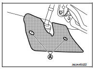
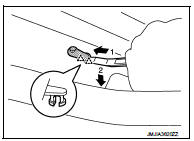
12. Remove column hole cover.
Disengage trim clips (A), and then remove column hole cover.
13. Remove dash side finisher (LH and RH). Refer to INT-20, "DASH SIDE FINISHER : Removal and Installation".
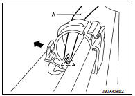
14. Disengage pawl using a remover tool (A) and open the harness clip.
 : Pawl
15. Remove floor carpet.
NOTE
:
Disengage pawls using a remover tool and remove carpet hook.
 : Pawl
INSTALLATION
Note the following item, and install in the reverse order of removal.
CAUTION:
Replace diagnosis sensor unit fixing bolts with a new part after removal. Never
reuse diagnosis sensor
unit fixing bolts.
 Body side trim
Exploded View
1. Rear body side welt
2. Center pillar upper garnish
3. Front body side welt
4. Front pillar garnish
5. Metal clip
6. Dash side finisher
7. Harness clip
8. Front kicking ...
 Headlining
Exploded View
LHD models
1. Headlining assembly
2. Assist grip clip
3. Rear assist grip RH
4. Front assist grip RH
5. Sun visor assembly RH
6. Sun visor cover RH
7. Sun visor cover LH
...
Other materials:
Corrosion protection
Most common factors contributing to vehicle corrosion
The persistent accumulation of moisture-retaining dirt, road grime, and organic debris within hidden body panel sections, structural cavities, and hard-to-reach areas of your Nissan Leaf.
Compromised integrity of the facto ...
Draining
1. Run the vehicle to warm up the transfer unit sufficiently.
2. Stop the engine and remove the drain plug (1) and gascket to
drain the transfer oil.
3. Before installing drain plug, set a new gasket. Install drain plug
on the transfer and tighten to the specified torque. Refer to DLN-
113, &qu ...
Exhaust gas (carbon monoxide)
WARNING
ŌĆó Do not breathe exhaust gases; they contain colorless and odorless carbon
monoxide. Carbon monoxide is dangerous. It can cause unconsciousness or death.
ŌĆó If you suspect that exhaust fumes are entering the vehicle, drive with all windows
fully open, and have the vehicle inspected ...
