Nissan Juke Service and Repair Manual : Front door finisher
Exploded View
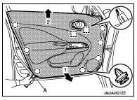
LHD models
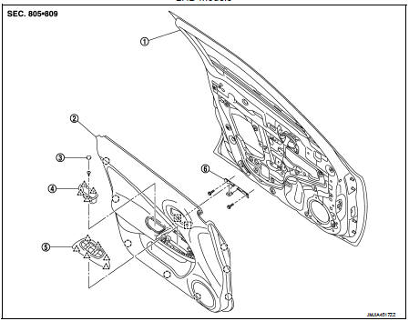
1. Front door panel
2. Front door finisher
3. Cap
4. Pull handle
5. Power window switch finisher
6. Pull handle bracket
 : Clip
 : Pawl
 : Metal clip
Removal and Installation
REMOVAL
CAUTION:
• When removing, always use a remover tool that is made of plastic.
• Never damage the door panel.
1. Fully open door window.
2. Remove pull handle.
1. Remove cap from the pull handle.
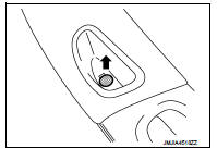
2. Remove pull handle fixing screw.
3. Lift up the pull handle while rotating it in direction indicated by the arrow as shown in the figure. Disengage pawls and remove the pull handle.
 : Pawl
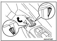
3. Remove power window switch finisher and power window switch as a unit.
1. Disengage power window switch finisher fixing pawls with a remover tool (A).
 Pawl
Pawl
CAUTION:
Apply protective tape (B) on the part to protect it from
damage.
2. Pull up power window switch finisher and power window switch as a unit and disconnect harness connector.
4. Remove front door corner cover. Refer to MIR-43, "DOOR MIRROR ASSEMBLY : Removal and Installation".
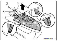
5. Remove front door finisher.
1. Disengage front door finisher fixing clips and metal clips with a remover tool (A).
 : Clip
 : Metal clip
CAUTION:
Insert a remover tool between body side panel and clip
and disengage pawl.
2. Pull toward the direction of the arrows as shown in the figure to remove.
NOTE
:
Remove power window switch. Refer to PWC-44, "Removal and Installation".
INSTALLATION
Note the following item, and install in the reverse order of removal.
CAUTION:
When installing front door finisher, check that clips, and metal clips are
securely in body panel holes,
and press them in.

 Rear door finisher
Exploded View
1. Rear door panel
2. Grommet
3. Rear door corner cover inner
4. Cap
5. Power window switch finisher
6. Rear door finisher
: Clip
: Pawl
: Metal clip
Removal and Installa ...
Other materials:
Hoses
HOSE REMOVAL AND INSTALLATION
• To prevent damage to rubber hose, do not pry off rubber hose with
tapered tool or screwdriver.
• To reinstall the rubber hose securely, check that hose insertion
length and orientation is correct. (If tube is equipped with hose
stopper, insert rubber hose i ...
Intelligent Key operating range
The Intelligent Key functions can only be used when the Intelligent Key is within
the specified operating range from the request switch 1 .
When the Intelligent Key battery is discharged or strong radio waves are present
near the operating location, the Intelligent Key system’s operating ra ...
Diagnosis system (BCM)
Common item
COMMON ITEM : CONSULT-III Function (BCM - COMMON ITEM)
APPLICATION ITEM
CONSULT-III performs the following functions via CAN communication with BCM.
SYSTEM APPLICATION
BCM can perform the following functions for each system.
NOTE:
It can perform the diagnosis modes except the fo ...
