Nissan Juke Service and Repair Manual : U0073 communication bus A off
Description
CAN (Controller Area Network) is a serial communication line for real-time application. It is an on-vehicle multiplex communication line with high data communication speed and excellent malfunction detection ability.
Many electronic control units are equipped onto a vehicle, and each control unit shares information and links with other control units during operation (not independently). In CAN communication, control units are connected with 2 communication lines (CAN-H line, CAN-L line) allowing a high rate of information transmission with less wiring. Each control unit transmits/receives data but selectively reads required data only.
DTC Logic
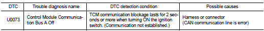
DTC DETECTION LOGIC
DTC CONFIRMATION PROCEDURE
1.PREPARATION BEFORE WORK
If another ŌĆ£DTC CONFIRMATION PROCEDUREŌĆØ occurs just before, turn ignition switch OFF and wait for at least 10 seconds, then perform the next test.
>> GO TO 2.
2.PERFORM DTC CONFIRMATION PROCEDURE
 With CONSULT-III
1. Start the engine and wait for at least 5 seconds.
2. Check the DTC.
Is ŌĆ£U0073ŌĆØ detected? YES >> Go to TM-384, "Diagnosis Procedure".
NO >> INSPECTION END
Diagnosis Procedure
For the diagnosis procedure, refer to LAN-17, "Trouble Diagnosis Flow Chart".

 U0100 lost communication (ECM A)
Description
CAN (Controller Area Network) is a serial communication line for real-time
application. It is an on-vehicle multiplex
communication line with high data communication speed and excellen ...
Other materials:
Engine stand setting
Preparing the engine to be on the stand
Before the engine is mounted on the engine sub-attachment, the engine's
electrical harness must be removed
and the engine oil drained.
1. Remove the multifunction support.
2. Remove the coolant inlet pipe on the water pump.
3. Place the rods (A), ...
Precaution Necessary for Steering Wheel Rotation after Battery Discon
NOTE:
ŌĆó Before removing and installing any control units, first turn the ignition
switch to the LOCK position, then disconnect
both battery cables.
ŌĆó After finishing work, confirm that all control unit connectors are connected
properly, then re-connect both
battery cables.
ŌĆó Always us ...
Water hose
Exploded View
1. Hose clamp
2. Water hose
A. Water outlet
B. Oil warm
Removal and Installation
REMOVAL
WARNING:
Never remove the radiator cap when the engine is hot. Serious burns could occur
from high pressure
coolant escaping from the radiator.
CAUTION:
Perform these steps after t ...
