
Nissan Juke Service and Repair Manual : P17BB primary pressure solenoid
DTC Logic
DTC DETECTION LOGIC
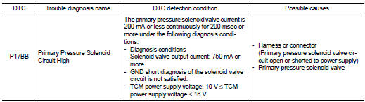
DTC CONFIRMATION PROCEDURE
1.PREPARATION BEFORE WORK
If another "DTC CONFIRMATION PROCEDURE" occurs just before, turn ignition switch OFF and wait for at least 10 seconds, then perform the next test.
>> GO TO 2.
2.CHECK DTC DETECTION
1. Start the engine and wait for 5 seconds or more.
2. Check the first trip DTC.
Is “P17BB� detected? YES >> Go to TM-459, "Diagnosis Procedure".
NO >> INSPECTION END
Diagnosis Procedure
1.CHECK CIRCUIT BETWEEN TCM AND THE CVT UNIT
1. Turn ignition switch OFF.
2. Disconnect the TCM connector and the CVT unit connector.
3. Check the continuity between the TCM harness connector terminal and the CVT unit harness connector terminal.

Is the inspection result normal? YES >> GO TO 2.
NO >> Repair or replace the malfunctioning parts.
2.CHECK PRIMARY PRESSURE SOLENOID VALVE
Check the primary pressure solenoid valve. Refer to TM-460, "Component Inspection (Primary Pressure Solenoid Valve)".
Is the inspection result normal? YES >> Check intermittent incident. Refer to GI-42, "Intermittent Incident".
NO >> Repair or replace the malfunctioning parts.
Component Inspection (Primary Pressure Solenoid Valve)
1.CHECK PRIMARY PRESSURE SOLENOID VALVE
Check the resistance between the CVT unit connector terminal and ground.
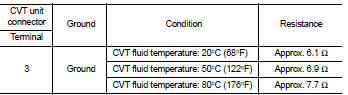
Is the inspection result normal? YES >> INSPECTION END
NO >> There is a malfunction of the primary pressure solenoid valve. Replace the transaxle assembly.
Refer to TM-508, "Removal and Installation".
 P17Ba primary pressure solenoid
DTC Logic
DTC DETECTION LOGIC
DTC CONFIRMATION PROCEDURE
1.PREPARATION BEFORE WORK
If another "DTC CONFIRMATION PROCEDURE" occurs just before, turn ignition
switch OFF and wait for a ...
 P2765 clutch B speed sensor
DTC Logic
DTC DETECTION LOGIC
DTC CONFIRMATION PROCEDURE
CAUTION:
Be careful of the driving speed.
1.PREPARATION BEFORE WORK
If another "DTC CONFIRMATION PROCEDURE" occurs just befor ...
Other materials:
Inspection
INSPECTION AFTER REMOVAL
Appearance
Check the propeller shaft for bend and damage. If damage is detected, replace
propeller shaft assembly.
Propeller Shaft Runout
Check propeller shaft runout at measuring points with a dial indicator.
If runout exceeds specifications, replace propeller sh ...
Radiator : Inspection
Check radiator for mud or clogging. If necessary, clean radiator as follows.
CAUTION:
• Be careful not to bend or damage radiator fins.
• When radiator is cleaned without removal, remove all surrounding parts such as
radiator cooling fan
assembly and horns. Then tape harness and harness ...
Audible reminders
Brake pad wear warning
Your disc brake pads are engineered with audible wear indicators. When a brake pad has reached its service limit and requires replacement, it will emit a distinct high-pitched scraping noise while the vehicle is in motion.
Initially, this sound may only be audible wh ...
