Nissan Juke Service and Repair Manual : P17Ba primary pressure solenoid
DTC Logic
DTC DETECTION LOGIC
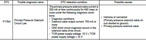
DTC CONFIRMATION PROCEDURE
1.PREPARATION BEFORE WORK
If another "DTC CONFIRMATION PROCEDURE" occurs just before, turn ignition switch OFF and wait for at least 10 seconds, then perform the next test.
>> GO TO 2.
2.CHECK DTC DETECTION
1. Start the engine and wait for 5 seconds or more.
2. Check the first trip DTC.
Is “P17BA” detected? YES >> Go to TM-457, "Diagnosis Procedure".
NO >> INSPECTION END
Diagnosis Procedure
1.CHECK CIRCUIT BETWEEN TCM AND THE CVT UNIT
1. Turn ignition switch OFF.
2. Disconnect the TCM connector and the CVT unit connector.
3. Check the continuity between TCM harness connector terminal and ground.
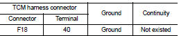
Is the inspection result normal? YES >> GO TO 2.
NO >> Repair or replace the malfunctioning parts.
2.CHECK PRIMARY PRESSURE SOLENOID VALVE
Check the primary pressure solenoid valve. Refer to TM-458, "Component Inspection (Primary Pressure Solenoid Valve)".
Is the inspection result normal? YES >> Check intermittent incident. Refer to GI-42, "Intermittent Incident".
NO >> Repair or replace the malfunctioning parts.
Component Inspection (Primary Pressure Solenoid Valve)
1.CHECK PRIMARY PRESSURE SOLENOID VALVE
Check the resistance between the CVT unit connector terminal and ground.
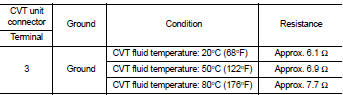
Is the inspection result normal? YES >> INSPECTION END
NO >> There is a malfunction of the primary pressure solenoid valve. Replace the transaxle assembly.
Refer to TM-508, "Removal and Installation".
 P17B8 high clutch solenoid
DTC Logic
DTC DETECTION LOGIC
DTC CONFIRMATION PROCEDURE
1.PREPARATION BEFORE WORK
If another "DTC CONFIRMATION PROCEDURE" occurs just before, turn ignition
switch OFF and wait for a ...
 P17BB primary pressure solenoid
DTC Logic
DTC DETECTION LOGIC
DTC CONFIRMATION PROCEDURE
1.PREPARATION BEFORE WORK
If another "DTC CONFIRMATION PROCEDURE" occurs just before, turn ignition
switch OFF and wait for a ...
Other materials:
Cleanliness
Cleanliness
RISKS ASSOCIATED WITH CONTAMINATION
The high pressure direct injection system is highly sensitive to
contamination. The risks associated with contamination
are:
• damage to or destruction of the high pressure injection system,
• components jamming,
• components losing seal ...
Rear door
Exploded View
1. Rear door panel
2. Door hinge (upper)
3. Door hinge (lower)
4. Door check link
5. Door striker
6. TORX bolt
: Do not reuse
: N·m (kg-m, in-lb)
N·m (kg-m, ft-lb)
: Body grease
Door assembly
DOOR ASSEMBLY : Removal and Installation
CAUTION:
• Perform work with ...
Engine cooling system
The engine cooling system is filled at the factory with a pre-diluted mixture
of 50% Genuine NISSAN Long Life Antifreeze/Coolant (blue) and 50% water to provide
year-round anti-freeze and coolant protection. The anti-freeze solution contains
rust and corrosion inhibitors. Additional engine coo ...
