Nissan Juke Service and Repair Manual : P2765 clutch B speed sensor
DTC Logic
DTC DETECTION LOGIC
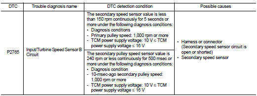
DTC CONFIRMATION PROCEDURE
CAUTION:
Be careful of the driving speed.
1.PREPARATION BEFORE WORK
If another "DTC CONFIRMATION PROCEDURE" occurs just before, turn ignition switch OFF and wait for at least 10 seconds, then perform the next test.
>> GO TO 2.
2.CHECK DTC DETECTION
1. Start the engine.
2. Drive the vehicle.
3. Maintain the following conditions for 10 seconds or more.
Selector lever : “D” position Vehicle speed : 55 km/h (34 MPH) or more
4. Stop the vehicle
5. Check the first trip DTC.
Is “P2765” detected? YES >> Go to TM-461, "Diagnosis Procedure".
NO >> INSPECTION END
Diagnosis Procedure
1.CHECK SECONDARY SPEED SENSOR POWER CIRCUIT
1. Turn ignition switch OFF.
2. Disconnect secondary speed sensor connector.
3. Turn ignition switch ON.
4. Check the voltage between the secondary speed sensor harness connector terminal and ground.
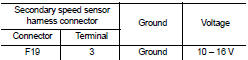
Is the inspection result normal? YES >> GO TO 2.
NO >> GO TO 6.
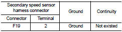
2.CHECK SECONDARY SPEED SENSOR GROUND CIRCUIT
Check continuity between of the primary speed sensor harness connector terminal and ground.
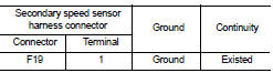
Is the inspection result normal? YES >> GO TO 3.
NO >> Repair or replace the malfunctioning parts.
3.CHECK CIRCUIT BETWEEN SECONDARY SPEED SENSOR AND TCM (PART 1)
1. Turn ignition switch OFF.
2. Disconnect the TCM connector.
3. Check continuity between the secondary speed sensor harness connector terminal and the TCM harness connector terminal.
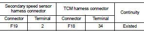
Is the inspection result normal? YES >> GO TO 4.
NO >> Repair or replace the malfunctioning parts.
4.CHECK CIRCUIT BETWEEN SECONDARY SPEED SENSOR AND TCM (PART 2)
Check continuity between the secondary speed sensor harness connector terminal and ground.
Is the inspection result normal? YES >> GO TO 5.
NO >> Repair or replace the malfunctioning parts.
5.CHECK TCM INPUT SIGNALS
1. Connect all of the disconnected connectors.
2. Lift the vehicle.
3. Start the engine.
4. Check frequency of secondary speed sensor.
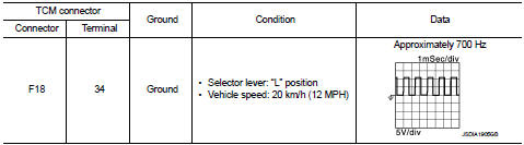
Is the inspection result normal? YES >> Check intermittent incident. Refer to GI-42, "Intermittent Incident".
NO >> Replace the secondary speed sensor. TM-496, "Removal and Installation".
6.CHECK CIRCUIT BETWEEN IPDM E/R AND SECONDARY SPEED SENSOR (PART 1)
1. Disconnect the IPDM E/R connector.
2. Check continuity between IPDM E/R harness connector terminal and secondary speed sensor harness connector terminal.
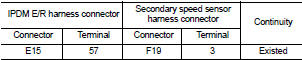
Is the check result normal? YES >> GO TO 7.
NO >> Repair or replace the malfunctioning parts.
7.CHECK CIRCUIT BETWEEN IPDM E/R AND SECONDARY SPEED SENSOR (PART 2)
Check continuity between IPDM E/R harness connector terminal and ground.
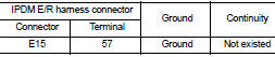
Is the check result normal? YES >> GO TO 8.
NO >> Repair or replace the malfunctioning parts.
8.DETECTION OF MALFUNCTION ITEMS
Check the following items: • Harness open circuit or short circuit between the ignition switch and IPDM E/R. Refer to PG-15, "Wiring Diagram - IGNITION POWER SUPPLY -".
• 10A fuse (No.55, IPDM E/R). Refer to PG-25, "Fuse, Connector and Terminal Arrangement".
• IPDM E/R
Is the check result normal? YES >> Check intermittent incident. Refer to GI-42, "Intermittent Incident".
NO >> Repair or replace the malfunctioning parts.
 P17BB primary pressure solenoid
DTC Logic
DTC DETECTION LOGIC
DTC CONFIRMATION PROCEDURE
1.PREPARATION BEFORE WORK
If another "DTC CONFIRMATION PROCEDURE" occurs just before, turn ignition
switch OFF and wait for a ...
 Main power supply and ground circuit
Diagnosis Procedure
1.CHECK TCM POWER CIRCUIT 1
1. Turn the ignition switch OFF.
2. Disconnect the TCM connector.
3. Check the voltage between the TCM harness connector terminals and ground.
Is ...
Other materials:
System
System Description
SYSTEM DIAGRAM
• The multi display unit transmits the operation status of the drive mode
switch to other units via CAN communication
as the mode signal (refer below).
- NORMAL: ON/OFF
- SPORT: ON/OFF
- ECO: ON/OFF
• Based on the mode signals received from TCM (CVT ...
Front disc brake
Brake pad : Inspection and Adjustment
INSPECTION
Check brake pad wear thickness from an inspection hole on cylinder
body. Check using a scale if necessary.
Wear thickness : Refer to BR-71, "Front Disc Brake".
ADJUSTMENT
Burnish contact surfaces between disc rotor and brake pads acc ...
Push-button power switch
WARNING
Do not attempt to operate or cycle the push-button power switch while actively driving the vehicle except in a verified, extreme emergency situation. (The primary EV powertrain system completely shuts down and cuts propulsion when the power switch is pushed rapidly three conse ...
